YV180X_Mainte_E.pdf - 第58页
3 -21 Service Manual Chapter 3 SED8013110 3 Machine data edit mode 6. Precision When “ Precision ” is selected from the <3/2/MCH_D A T A> main menu, the submenu appears as sho wn belo w . Data entered here ar e of …
3
-20
Service Manual
Chapter 3
3
Machine data edit mode
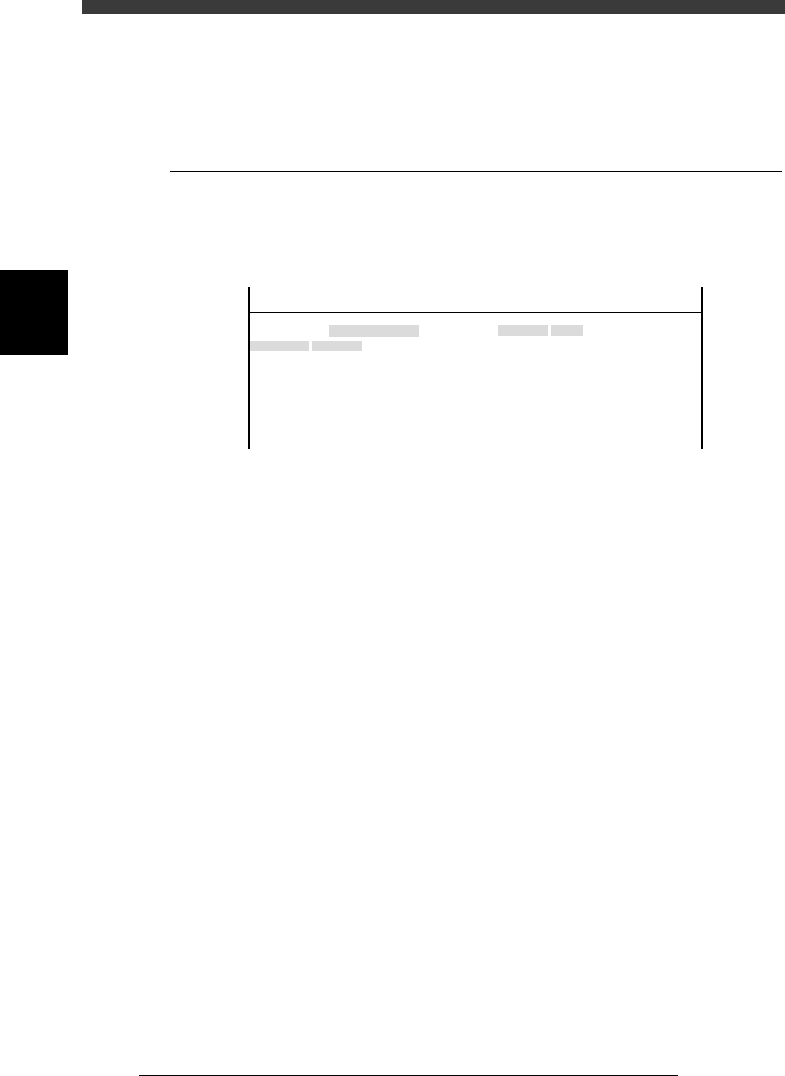
5. Other
Selecting “Other” - “RS-232C Port” shows the communication protocol
settings.
5.1 RS-232C
Communication protocols can be specified on this screen. Use the same
protocol settings as the other side to be communicated.
RS-232C protocols
47318-C0-00
Object
Time-out
CR/CRLF
Flow CTRL.
BaudRate
Parity
Stop Bit
Data Bits
Value
No
CR
XON/OFF
9600
0dd
1bit
8bits
OBJECT
RS-232C Port
TCH. UNIT SPEED
- - - - - - - -
<<<APPLICATION>>> 3/MAINTE/M
<<MODE>> 2/MCH_DATA
3
-21
Service Manual
Chapter 3
SED8013110
3
Machine data edit mode
6. Precision
When “Precision” is selected from the <3/2/MCH_DATA> main menu, the
submenu appears as shown below. Data entered here are offset parameters
for correcting mounting accuracy and multi camera marker settings for
maintaining .high recognition accuracy.
Submenu box when “Precision” is selected
47319-D8-00
SUB MENU
Zigzag Param.
Parallel Param.
Rotation Param.
MultiCam Marker
MCHDATA SORT
Head
Camera
Machine
Tray Changer
Station
Other
Precision
Spare Data
<<<APPLICATION>>> 3/MAINTE/M
<<MODE>> 2/MCH_DATA
Camera
Camera1
Camera2
Camera3
Camera4
Camera5
Camera6
Camera7
Camera8
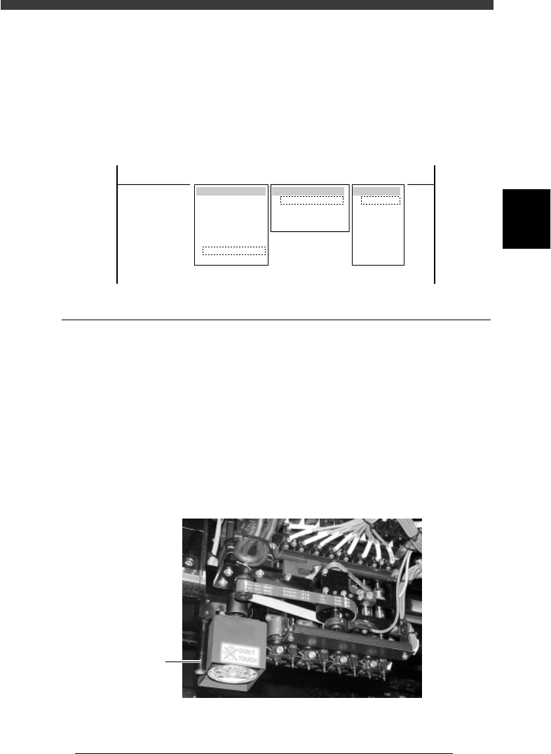
6.1 MultiCam Marker
Selecting “MultiCam Marker” from the “Precision” submenu opens the
MultiCam Marker screen showing the offset position of the reference
marker relative to Head 1 and related parameters.
When this function is enabled, the machine recognizes components by
using the reference marker provided on the head assembly. Adverse effects
from mechanical changes over time on recognition accuracy can be
minimized. To use this function with the YV180X, set the MultiCam.
Marker parameter to “Marker 2” on the detail menu in OPTION CONFIG.
mode and to “Use” in component information.
Multi camera marker of YV180X
43302-D8-00
Marker

3
-22
Service Manual
Chapter 3
3
Machine data edit mode
MultiCam Marker screen
47320-D8-00
Coord. 1
0.000
182.000
0.000
0.000
0.000
0.000
0.000
0.000
0.000
0.000
0 000
Object
Maker 1 Offset
Maker 2 Offset
Maker Window
Cam3 Datym +
Cam3 Datym -
Cam4 Datym +
Cam4 Datym -
Cam5 Datym +
Cam5 Datym -
Cam6 Datym +
C6Dt
OBJECT
MultiCam Marker
TCH. UNIT SPEED
- - - - - - - -
A
A
A
A
A
A
A
A
A
A
A
Coord. 2
10.000
0.000
8.000
0.000
0.000
0.000
0.000
0.000
0.000
0.000
0 000
Coord. 3
0.000
0.000
0.000
0.000
-0.135
-0.138
0.000
0 000
Coord. 4
980
0.000
0.000
0.000
0.000
0.000
0.000
0.000
0 000
Option
255
<<<APPLICATION>>> 3/MAINTE/M
<<MODE>> 2/MCH_DATA
Marker Offset - Coord.1, Coord 2
XY offset of the reference marker on the head assembly, relative to Head
1.
Marker Window Window size used to recognize the reference
marker.
Cam Datum + Offset position measured by moving the reference
marker in the left-to-right direction above the
camera.
Cam Datum - Offset position measured by moving the reference
marker in the right-to-left direction above the
camera.
n
NOTE
“Cam Datum +” and “Cam Datum -” parameters can be automatically adjusted by
running the Marker command in MCH_ADUST mode.