YV180X_Mainte_E.pdf - 第68页
4 -10 Service Manual Chapter 4 SED8013110 4 Machine adjust mode 3. Adjust tar get <3/3/B1> When you select <3/3/ MCH_ ADJUST> − <B1 ADJUST T ARGET>, the adjustment menu window appears as sho wn below . …
4
-9
SED8013110
Service Manual
Chapter 4
4
Machine adjust mode
2.7 Search origin
<3/3/A8>
The <3/3/A8 SEARCH ORIGIN> command returns each axis to its origin
position. After power is turned on, return-to-origin must be performed
before beginning any work.
This command is also provided in the MANUAL mode of each application
manager. To perform return-to-origin again after having performed it once,
line up the cursor with <3/4/B6 INIT. SERVO ORIGIN> and press the
[SHIFT]+[ENTER] keys. The machine reference for each axis also appears
on the operation monitor after return-to-origin is complete.
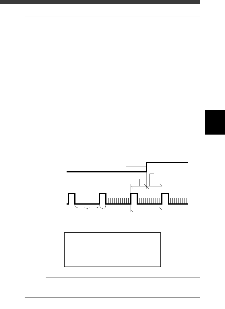
Machine reference
The built-in motor encoder of each axis issues a “0” pulse each time one
rotation is complete. When return-to-origin is performed, there will be a
difference in distance between the position where the origin signal is
detected and the point at which the next encoder “0” pulse is received
(origin position is actually set). This is called the machine reference and is
usually expressed as a percentage, with 100% being equal to one full
rotation of the motor. The machine reference value must be in the range
from 35% to 65%.
Machine reference
43402-D8-00
Encoder signal
Origin sensor
signal
Machine reference (Z axis)
Origin signal
One rotation of motor
A, B phase 0 phase
Machine reference
(W, X, Y, T, R axes
)
Machine reference display
47409-D8-00
Machine Reference
Hit Any Key.
X1 = 55 %
W2 = 52 %
X2 = 48 %
W1 = 50 %
Y1 = 55 %
W2 = 52 %
Y2 = 48 %
W4 = 50 %
Z1 = 55 %
T1 =52 %
Z2 = 48 %
R1 = 55 %
R2=52 %
n
NOTE
The machine reference of each axis is preadjusted at the factory prior to shipping. It is
unlikely that you will need to readjust these values under normal operating conditions. If
readjustment is required, please contact your YAMAHA sales office or dealer.
4
-10
Service Manual
Chapter 4
SED8013110
4
Machine adjust mode
3. Adjust target
<3/3/B1>
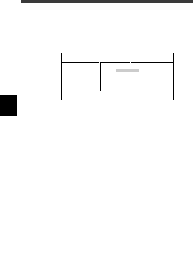
When you select <3/3/ MCH_ ADJUST> − <B1 ADJUST TARGET>, the
adjustment menu window appears as shown below. Each adjustment item
and is described in the following sections.
Adjustment menu window in Machine Adjust mode
47410-D8-00
<<<APPLICATION>>> 3/MAINTE/M
<<MODE>> 3/MCH_ADJUST
<COMMAND_LIST> B/SAVE & QUIT
B1 ADJUST TARGET
Object
Soft. Limit
Position
Vacuum Level
Moving Camera
Multi Camera
R Axis Accuracy
Mount Feedback
4
-11
SED8013110
Service Manual
Chapter 4
4
Machine adjust mode
3.1 Software limits
When you select <3/3/B1 ADJUST TARGET> - “Soft Limit”, the Software
Limit screen opens as shown below. You can check and adjust here the
software limit parameters to determine the axis movement range and initial
position parameters used as a reference point for axis movement.
These parameters must be set correctly to maintain accurate machine
movement and component mounting.
Software Limit screen
47458-D8-00
<<<APPLICATION>>> 3/MAINTE/M
<<MODE>> 2/MCH_DATA
OBJECT
Software Limit
TCH.UNIT SPEED
- - - - - - - -
-direct.
-277.973
-272.227
-274.202
-283.200
-0.238
-0.154
-32.840
-91.717
-88.200
-26.815
-36.140
-360.000
-360.000
Init. Pos
-323.600
-321.790
-323.650
-328.650
0.000
0.000
360.271
-25.815
448.199
15.100
11.000
Init. Mov
395.000
+direct.
11.323
13.753
11.993
7.113
23.477
23.076
842.547
942.344
943.970
452.790
449.199
360.000
360.000
Axis
W1/RIGHT
W2/A-TBL
W3/B-TBL
W4/LEFT
Z1/A-TBL
Z2/B-TBL
T1/MAIN
X1/A-TBL
X2/B-TBL
Y1/A-TBL
Y2/B-TBL
R1/A-TBL
R2/B-TBL
Reference
The Software Limit screen opens by selecting “Position” - “Soft Limit” in MCH_DATA
mode.
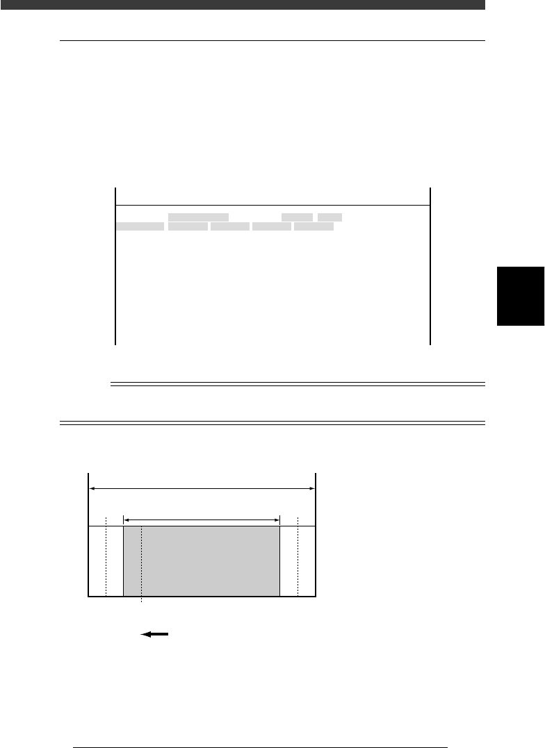
Software limits and axis movement range
43403-C0-00
A
A :
B :
C :
D :
E :
F :
Movable range
Movement range allowed
by software limits
Software limits
Secondary limits (X, Y)
Origin position
Mechanical limits
B
Return to ori
g
in direction
Mechanical stopper
Mechanical stopper
FDCE CDF
▲▲▲▲ ▲▲▲