YV180X_Mainte_E.pdf - 第97页
4 -39 SED8013110 Service Manual Chapter 4 4 Machine adjust mode 5 Check safety and press the [ENTER] key . The teaching screen appears. 47429-C0-00 CAUTION! The axes will move. Check that everything is safe, then press t…
4
-38
Service Manual
Chapter 4
SED8013110
4
Machine adjust mode
3.4.1 Adjusting the FOV & focus
The following explains how to adjust the FOV (field of view) and focus of
the moving camera. Prepare a PCB having obvious characters or marks that
can be used for focusing.
Reference
YAMAHA uses a glass PCB with minimal warp and distortion, specially designed for
adjustment work. To make more accurate adjustments, we recommend using this glass
PCB (sold separately).
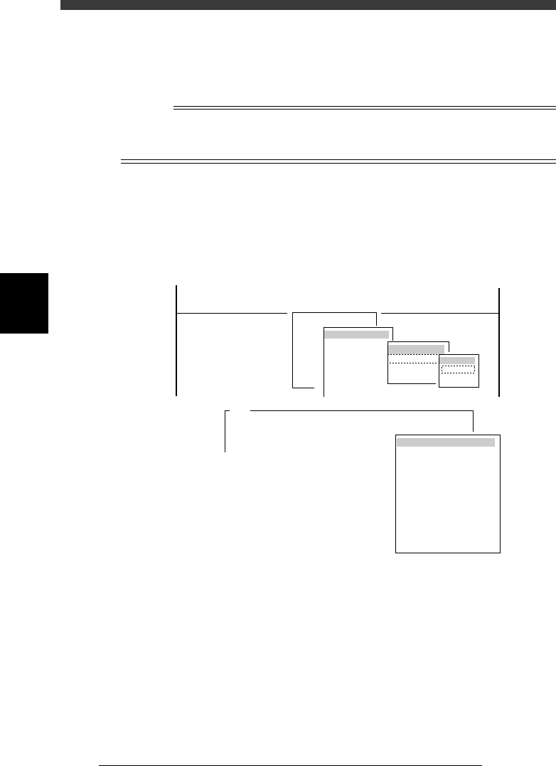
1 Run the “Moving Camera” - “FOV & Focus” command.
1. Select <3/3/B1 ADJUST TARGET> - “Moving Camera” - “FOV & Focus”
and press the [ENTER] key.
2. Select the conveyor table and press the [ENTER] key.
The CONVEYOR UNIT menu box appears.
47428-D8-00
A426
Please put the specified PCB at the mount position
with the conveyor unit utility.
After.....
(STS.)
OFF
OFF
OFF
OFF
OFF
OFF
OFF
OFF
OFF
OFF
LOCATE PIN
PUSH UP
PCB CLAMPE
EDGE CLAMP
PUSH IN
MAIN STOPPER
ENT. STOPPER
EXIT. STOPPER
CONV. MOTOR
CONV. WIDTH
PROGRAM PIN
RETURN
CONVEYOR UNIT
Target
FOV & Focus
Broghtness
Camera Scale
B1 ADJUST TARGET
Object
Moving Camera
<<<APPLICATION>>> 3/MAINTE/M
<<MODE>> 3/MCH_ADJUST
<COMMAND_LIST> B/SAVE & QUIT
Target
Atable
Btable
2 Set the PCB on the conveyor table.
See the mounter operation manual for how to clamp the PCB on the
conveyor.
Always press the emergency stop button before putting your hands in the
axis movement area.
3 Cancel emergency stop after clamping the PCB on the
conveyor.
Release the emergency stop button and press the [READY] button.
4 Select “RETURN” from the CONVEYOR UNIT menu.
You can also use the [ESC] key to exit the CONVEYOR UNIT menu.
4
-39
SED8013110
Service Manual
Chapter 4
4
Machine adjust mode
5 Check safety and press the [ENTER] key.
The teaching screen appears.
47429-C0-00
CAUTION! The axes will move.
Check that everything is safe, then press the [ENTER] ...
A303
<<<Teaching>>>
Please position the cross hair cursor over the
Light Adjuster...
A303
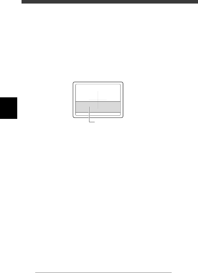
6 Position the target to be focused, in the center of the
screen.
Manipulate the YPU joystick to move the moving camera and conveyor
table so that the target to be focused is positioned in the center of the
screen.
7 Press the [ENTER] key and proceed to the next step.
e
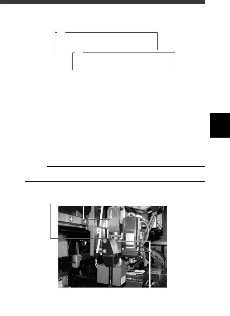
8 Press the emergency stop button and then adjust the FOV
and focus.
Loosen the two bolts clamping the moving camera lens tube (do not
remove them) and gradually move the camera body up or down so that
the best focus is obtained. (The FOV is set to an optimum range at this
point.) After adjusting the focus, tighten the two bolts to temporarily clamp
the lens tube.
Reference
If necessary, the lighting level can be adjusted during focus adjustment by using the UP
and Down arrow keys or [DEL] and [INS] keys.
Moving camera focus adjustment
43421-D8-00
Lens tube Moving camera
Loosen the two bolts and move the camera up or down
4
-40
Service Manual
Chapter 4
SED8013110
4
Machine adjust mode
9 Cancel emergency stop, then move the camera to above
the conveyor rail.
Manipulate the YPU joystick to move the camera so that the conveyor rail
is displayed near the middle of the vision monitor.
e
0 Press the emergency stop button, then adjust the camera
angle.
Rotate the camera body so that the conveyor rail is parallel to the cross
cursor on the vision monitor.
Adjustments of the moving camera focus (height), FOV and angle are now
complete.
Moving camera angle adjustment
43424-D8-00
Adjust the camera angle so that the conveyor
rail is parallel to the cross cursor.
q Tighten the two bolts to securely clamp the camera lens
tube.
Recheck the focus and angle after tightening the bolts.
w Follow the messages on the operation monitor to quit the
adjustment.
When the PCB on the conveyor table is unclamped, remove the PCB.
There is no machine data to be saved in this adjustment.