YV180X_Mainte_E.pdf - 第143页
6 -5 SED8013110 Service Manual Chapter 6 6 Conveyor unit and air supply unit adjustment 1 Open the output monitor in MANUAL mode. Select <3/4/A1 INPUT/OUTPUT MONIT OR> - ”SELECTION” - “CONVEYOR” and press the [ENTE…
6
-4
Service Manual
Chapter 6
SED8013110
6
Conveyor unit and air supply unit adjustment
1.1 Adjusting the air valve
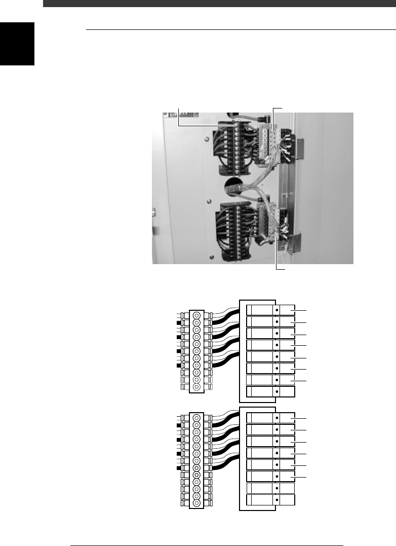
The air valve of each conveyor unit mechanism is located inside the lower
right panel on the back of the machine. Air drive speed can be adjusted by
turning the speed controller knob connected to each air valve.
Air valves for conveyor unit operation
43610-D8-00
Speed controller
Air valve
Air valve
Air valve
T1920 : Miain stopper
Orange : Ascent speed
Black : Descent speed
T1921 : Pushup
T1922 : Locate pin
T1923 : Edge clamp
T1930 : PCB clamp
T1926 : Exit stopper
T1925 : Entrance stopper
<
A table
>
T1932 : Miain stopper
T1933 : Pushup
T1934 : Locate pin
T1935 : Edge clamp
T1931 : PCB clamp
T1937 : Transfer hook
<
B Table
>
Speed controller
6
-5
SED8013110
Service Manual
Chapter 6
6
Conveyor unit and air supply unit adjustment
1 Open the output monitor in MANUAL mode.
Select <3/4/A1 INPUT/OUTPUT MONITOR> - ”SELECTION” -
“CONVEYOR” and press the [ENTER] key.
2 Check the speed of the conveyor unit you want to adjust.
Use the arrow keys to line up the cursor with the desired unit and press
the [ENTER] key.
The selected unit turns on and off each time you press the [ENTER] key
and the digit on the output monitor changes to “1” or “0”. The speed
should be around one second (speed at which components mounted on
the PCB in the preceding process do not shift).
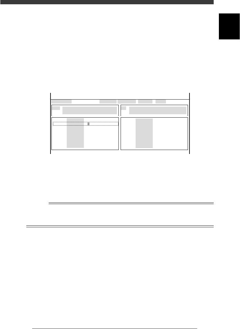
Output monitor example (A-table locate pins are raised)
47601-D8-00
CONV
CONV
CONV
CONV
CONV
CONV
CONV
CONV
OUT
0
0
0
0
0
0
00000000
00000000
0
0
0
0
0
0
0
0
IN
T1920
T1922
T1923
T1924
T1867
T1921
T4E60
T4E70
N1113
N1117
N1115
N1120
N1116
N1030
N1121
N1123
I/O MONITOR DISP. TYPE SELECTION
LOCATE PIN1 (A TABLE)
OFF 0 / ON 1
BUSY IN (GATE IN)
NOT DETECT 0 / DETECT 1
CONV
CONV
CONV
CONV
CONV
CONV
CONV
CONV
OBJECT CONV
<<<APPLICATION>>> 3/MAINTE/M
<<MODE>> 4/MANUAL
↑
↓↓
e
3 Press the emergency stop button, then adjust the speed.
Loosen the lock nut and turn the speed controller knob for the orange tube
to adjust the ascent speed, or turn the speed controller knob for the black
tube to adjust the descent speed. In either case, turning the knob to the left
increases the speed, while turning it to the right decreases the speed.
n
NOTE
The main stopper must ascend slightly earlier than the locate pins.
The ascent speed of the fixed locate pin should be slightly higher than the movable locate
pin.
4 Tighten the speed controller lock nut .
Use the same procedure when adjusting the operation speeds of other
conveyor units.
6
-6
Service Manual
Chapter 6
SED8013110
6
Conveyor unit and air supply unit adjustment
1.2 Conveyor speed
The conveyor speed varies according to the frequency of the power supply
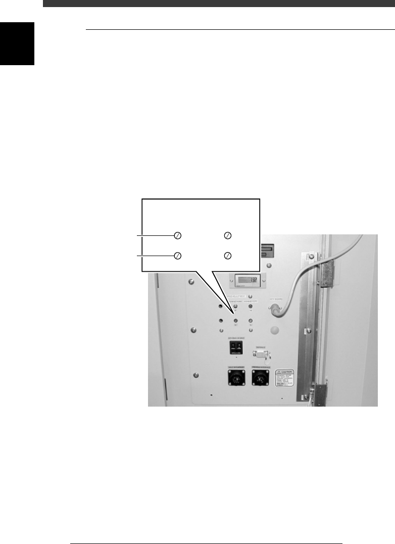
and the weight of the PCBs on the conveyor. You can adjust the carry-in
and carry-out conveyor speeds by using the adjustment screws located
inside the lower right panel on the front side.
The YV180X conveyor section is divided into 4 conveyors: carry-in
conveyor, B-table conveyor, A-table conveyor and carry-out conveyor. The
carry-in and carry-out conveyors each move at two different speeds: a high
speed (H) for reducing the transfer time of PCBs and a low speed (L) for
minimizing impact when the PCB hits the entrance stopper and exit
stopper. To adjust these speeds, prepare typical PCBs and use the proce-
dure below.
Conveyor speed adjustment screws
43611-D8-00
SPEED ADJUSTMENT
High speed
Low speed
CONVEYOR 2 CONVEYOR 1
HH
LL