YV180X_Mainte_E.pdf - 第113页
4 -55 SED8013110 Service Manual Chapter 4 4 Machine adjust mode 3.5.2 Adjusting the lighting level T o adjust the brightness lev el, y ou will need two custom tools (light adjuster plate: KM1-M8806-0XX and light adjuster…

4
-54
Service Manual
Chapter 4
SED8013110
4
Machine adjust mode
q Tighten the bolts to secure the camera.
e
Be sure to press the emergency stop button before this work. After
tightening the bolts, recheck the focus.
w Follow the message on the operation monitor to quit the
adjustment.
There is no machine data to be saved in this adjustment.
e
Remove the focus adjuster.
Be sure that the machine is in emergency stop and then remove the focus
adjuster.
4
-55
SED8013110
Service Manual
Chapter 4
4
Machine adjust mode
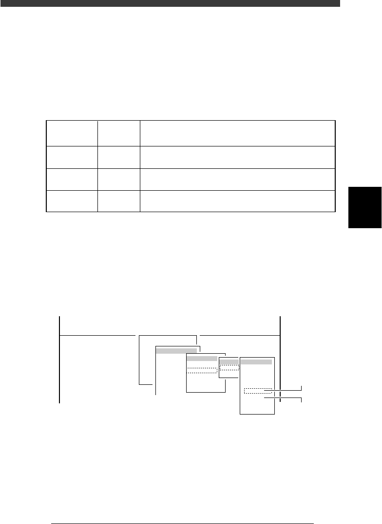
3.5.2 Adjusting the lighting level
To adjust the brightness level, you will need two custom tools (light
adjuster plate: KM1-M8806-0XX and light adjuster plate 2: KV7-M8806-
0XX) available from YAMAHA as options. The lighting pattern for the
multi-vision camera is divided into three zones: main, coaxial and side.
Follow the steps below to adjust the brightness in each zone.
Lighting pattern and allowable brightness range
45407-D8-00
Main
Coaxial
Side
Brightness in the light gray area on the two-tone side of
light adjuster plate (KM1-M8806-0XX)
Average brightness on the white side of light adjuster plate
(KM1-M8806-0XX)
Average brightness on the white side of light adjuster plate 2
(KV7-M8806-0XX)
Lighting
pattern
Brightness to be checked
Brightness
range
125 to 131
18 to 22
61 to 67
1 Run the “Multi Camera” − ”Brightness” command.
1. Select <3/3/B1 ADJUST TARGET> − ”Multi Camera” − “Brightness” and
press the [ENTER] key.
2. Select the conveyor table and the camera No. by pressing the [ENTER]
key.
The A-table multi-vision camera is designated “Cam. 5” and the B-table
multi-vision camera “Cam. 6”.
47445-D8-A0
B1 ADJUST TARGET
Object
Multi Camera
<<<APPLICATION>>> 3/MAINTE/M
<<MODE>> 3/MCH_ADJUST
<COMMAND_LIST> B/SAVE & QUIT
Target
FOV & Focus
Brightness
Camera Scale
Dual Recognition
Marker
table
A table
B table
Target
Cam. 1
Cam. 2
Cam. 3
Cam. 4
Cam. 5
Cam. 6
Cam. 7
Cam. 8
A Table
Multi Camera
B Table
Multi Camera
2 Check safety and press the [ENTER] key.
The head assembly moves to the component pickup point.
4
-56
Service Manual
Chapter 4
SED8013110
4
Machine adjust mode
e
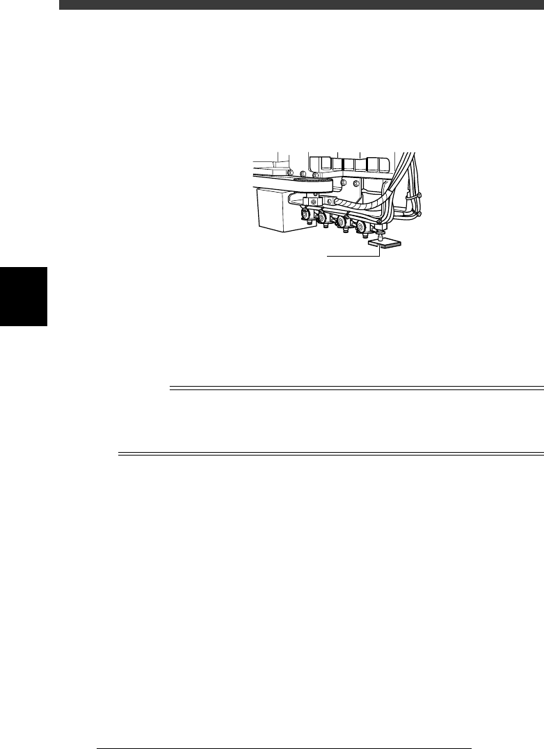
3 Press the emergency stop button, then attach the light
adjuster plate (KM1-M8806-0XX) to Head 1.
Attach the light adjuster plate to Head 1, with the two-tone surface facing
down. The light gray area should be displayed in the entire square window
on the vision monitor.
Attaching the light adjuster plate
43413-C0-00
Light adjuster plate
4 Cancel emergency stop.
Check safety, then release the emergency stop button by turning it
clockwise and press the [READY] button.
5 Check safety, then press the [ENTER] key again.
The head assembly moves and passes repeatedly over the multi-vision
camera and the main brightness level is automatically measured and
optimized. The lighting unit of the selected camera flashes at this time.
Reference
When the lighting level is successfully optimized, the measurement automatically stops. If
the measurement still continues even after the head assembly has passed repeatedly more
than 30 times over the camera, then repeat this adjustment from the beginning. If it fails
again, the lighting unit may be defective, so please contact us. (Same for Steps 7 and 9.)
e
6 Press the emergency button, then invert the light adjuster
plate.
Turn the light adjuster plate upside down and then reattach it to Head 1,
with the white surface facing down.
7 Cancel emergency stop and press the [ENTER] key.
The head assembly moves and passes repeatedly over the multi-vision
camera and the coaxial brightness level is automatically measured and
optimized.
At this point, the lighting unit of the selected camera flashes.
8 Change the light adjuster tool.
After pressing the emergency stop button, remove the light adjuster tool 1
from Head 1 and attach the light adjuster tool 2 (KV7-M8806-0XX) to
Head 1, with the mirror side facing up.
If the camera is not equipped with the side lighting unit, skip Steps 8 and
9.