YV180X_Mainte_E.pdf - 第110页
4 -52 Service Manual Chapter 4 SED8013110 4 Machine adjust mode 5 Check safety and press the [ENTER] key . The head assembly moves to the component pickup point. e 6 Press the emergency stop button, then attach the focus…
4
-51
SED8013110
Service Manual
Chapter 4
4
Machine adjust mode
3.5.1 Adjusting the FOV & focus
Use the following steps to adjust the FOV (field of view) and focus of the
multi-vision camera. Prepare in advance, a focus adjuster (KV1-M8803-
0XX).
1 Check the camera height and lighting method.
Select <3/2/Camera> − ”Coordinate/Spec” and press the [ENTER] key.
Check the “Z”, “Size” “Max Z” and “Light Sp” settings of the multi-vision
camera you are going to adjust.
47444-D8-00
<<<APPLICATION>>> 3/MAINTE/M
<<MODE>> 2/MCH_DATA
Cam No.
Cam 1A
Cam 3A
Cam 5A
Cam 2A
Cam 4B
Cam 6B
X
152.042
0.000
382.925
-152.051
0.000
472.334
OBJECT
Coordinate/Spec
TCH.UNIT SPEED
- - - - - - - -
Y
-0.166
0.000
0.091
0.446
0.000
-0.064
Z
0.000
0.000
17.140
0.000
0.000
17.390
R
-0.305
0.000
-0.386
-0.099
0.000
-0.515
Type
Move
- - - - - - - - - - - - -
Dig.Multi
Move
- - - - - - - - - - - - -
Dig.Multi
Size
0
0
45
0
0
45
Max Z
0
0
7
0
0
7
Light Sp
TypeA
TypeA
TypeG
TypeA
TypeA
TypeG
"Z" Nearly equal to the PCB height
"Size" 45 (mm)
"Max Z" 7 (mm)
"Li
g
ht Sp" Should be set to the correct type. (See Help.)
e
2 Attach a QFP nozzle to Head 1.
Press the emergency stop button and then attach a QFP nozzle (Type 74A)
to Head 1.
3 Cancel emergency stop.
Release the emergency stop button by turning it clockwise and press the
[READY] button.
4 Run the “Multi Camera” − "FOV & Focus" command.
1. Select <3/3/B1 ADJUST TARGET> − ”Multi Camera” − "FOV & Focus"
and press the [ENTER] key.
2. Select the conveyor table and the camera No. by pressing the [ENTER]
key.
The A-table multi-vision camera is designated “Cam. 5” and the B-table
multi-vision camera “Cam. 6”.
47445-D8-00
B1 ADJUST TARGET
Object
Multi Camera
<<<APPLICATION>>> 3/MAINTE/M
<<MODE>> 3/MCH_ADJUST
<COMMAND_LIST> B/SAVE & QUIT
Target
FOV & Focus
Brightness
Camera Scale
Dual Recognition
Marker
table
A table
B table
Target
Cam. 1
Cam. 2
Cam. 3
Cam. 4
Cam. 5
Cam. 6
Cam. 7
Cam. 8
A Table
Multi Camer
a
B Table
Multi Camer
a
4
-52
Service Manual
Chapter 4
SED8013110
4
Machine adjust mode
5 Check safety and press the [ENTER] key.
The head assembly moves to the component pickup point.
e
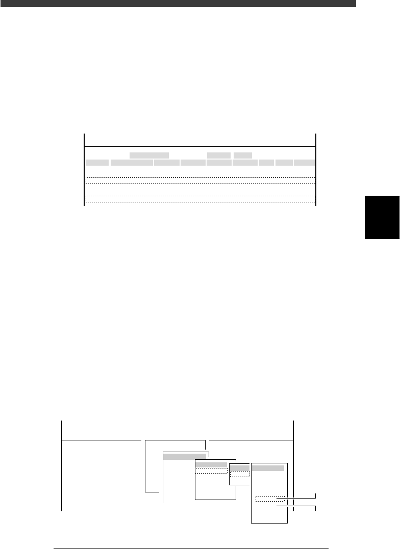
6 Press the emergency stop button, then attach the focus
adjuster tool to Head 1.
The scale pattern side must face downwards as shown below.
Attaching the focus adjuster tool
43410-D8-00
QFP nozzl
e
Focus adjuster tool
c
CAUTION
Attach the focus adjuster in the correct orientation as shown below. Otherwise, accurate
adjustment cannot be made. The orientation is correct when the image of the focus
adjuster pattern appears as shown in Step 8.
7 Cancel emergency stop.
Release the emergency stop button by turning it clockwise and press the
[READY] button on the YPU.
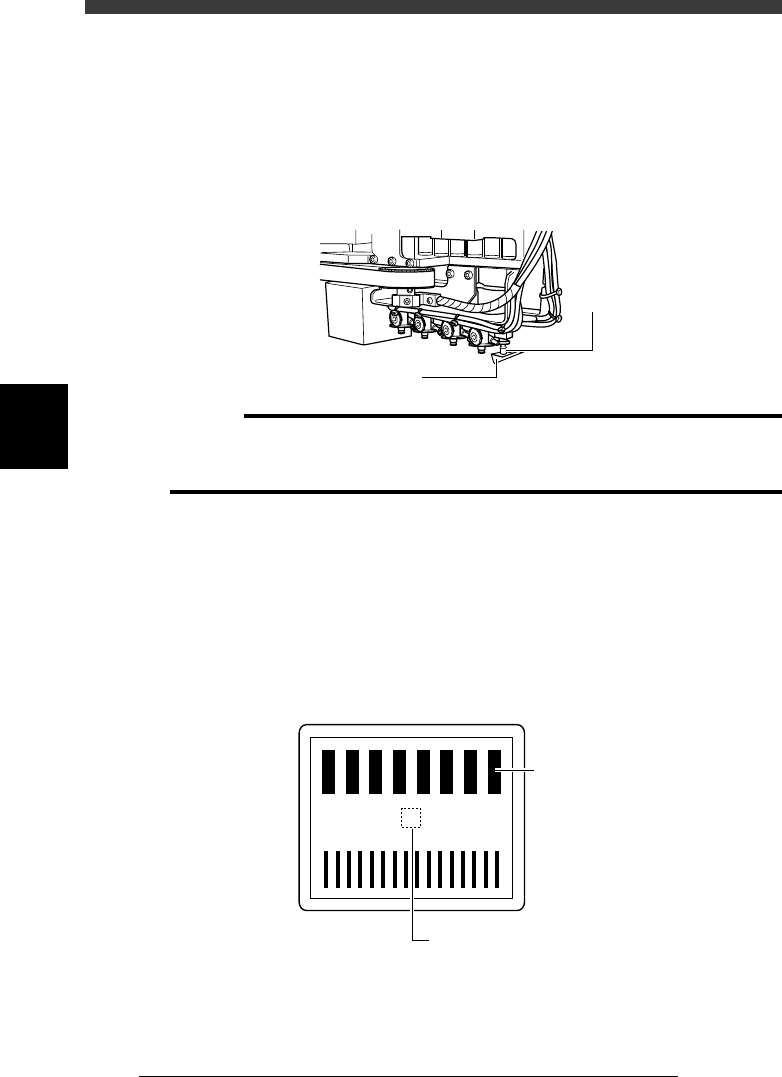
8 Check safety, then press the [ENTER] key again.
The head assembly moves and passes repeatedly over the multi-vision
camera and the image of the focus adjuster tool is displayed on the vision
monitor. Check that the scale “0” on the focus adjuster is focused.
Focus adjuster image
43411-D8-00
4
3
3
1
0
-1
-2
-3
-4
Thick lines should be
upper part of screen
Check that “0” is focused.
4
-53
SED8013110
Service Manual
Chapter 4
4
Machine adjust mode
e
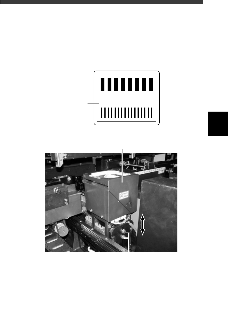
9 Press the emergency stop button and adjust the focus.
Loosen the two bolts securing the camera to the camera stand and then
adjust the camera installation height, so that the focus index value
displayed on the vision monitor is maximized. (At this point, the FOV is
set to optimum range.)
Tighten the bolts temporarily after adjusting the camera installation height.
Focus index value
43412-D8-00
4
3
2
1
0
-1
-2
-3
-3
160
Focus index
Multi-vision camera height (focus) adjustment
43423-D8-00
Multi-view camera
Loosen these bolts and move the camera upwards or downwards.
0 Cancel emergency stop and check the focus adjustment.
The image displayed on the vision monitor during this adjustment is an
image stored in the memory. It does not change as you adjust the camera
installation height. Cancel emergency stop to resume image acquisition
and check the adjustment result.
Repeat Steps 9 and 10 until the best focus is obtained.