YV180X_Mainte_E.pdf - 第127页
4 -69 SED8013110 Service Manual Chapter 4 4 Machine adjust mode 5 Enter the component database No. and press the [ENTER] key . Enter here the database number of the component you have prepared. 47455-C0-00 Please input t…
4
-68
Service Manual
Chapter 4
SED8013110
4
Machine adjust mode
To determine these offset settings, use the R Axis Accuracy command in
the Maintenance Manager. The machine automatically evaluates these
offset settings by recognizing the component that a head picks up while
rotating the nozzle shaft at the four angles of 0, 180, 90 and -90 degrees.
n
NOTE
If the reference mounting angle itself has deviated, the camera angle (R coordinate in the
CameraCoordinate parameters) must be corrected.
1 Prepare a component to be used as a reference.
Use a relatively large, popular component of known size which is
registered in the component database.
Reference
SOP components such as “No.704; SOP16-P1.27-6.4W” are recommended. If you are
going to use tape feeder components, install the tape feeder on the feeder plate in
advance.
e
2 Press the emergency stop button, then attach the nozzle
that matches the component.
You can skip this step for FNC heads.
3 Cancel emergency stop.
Check safety, then release the emergency stop button and press the
[READY] button.
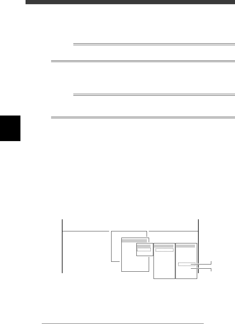
4 Run the R Axis Accuracy command.
1. Select <3/3/B1 ADJUST TARGET> - "R Axis Accuracy" and press the
[ENTER] key.
2. Select the conveyor table, head No. and camera No. by pressing the
[ENTER] key.
The A-table multi-vision camera is designated “Cam. 5” and the B-table
multi-vision camera “Cam. 6”.
47454-D8-00
B1 ADJUST TARGET
Object
R Axis Accuracy
<<<APPLICATION>>> 3/MAINTE/M
<<MODE>> 3/MCH_ADJUST
<COMMAND_LIST> B/SAVE & QUIT
Target
A table
B table
Target
Cam. 1
Cam. 2
Cam. 3
Cam. 4
Cam. 5
Cam. 6
Cam. 7
Cam. 8
Head No
Head 1
Head 2
Head 3
Head 4
Head 5
Head 6
Head 7
Head 8
A Table
Multi Camer
a
B Table
Multi Camer
a
4
-69
SED8013110
Service Manual
Chapter 4
4
Machine adjust mode
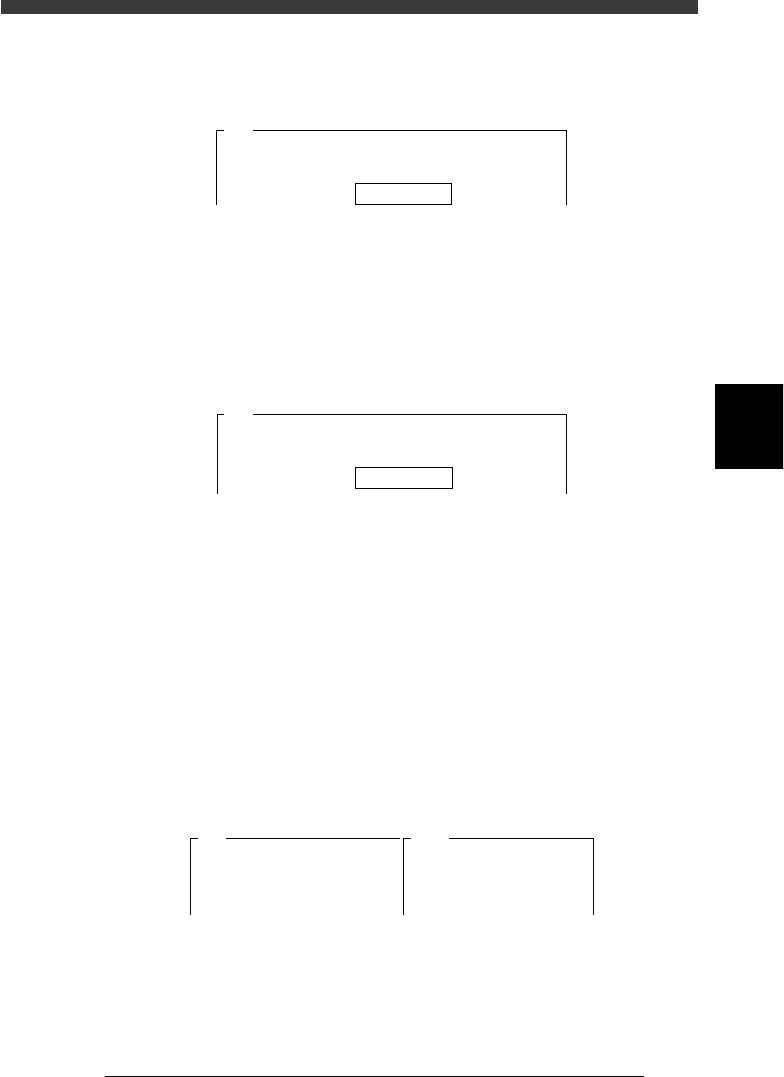
5 Enter the component database No. and press the [ENTER]
key.
Enter here the database number of the component you have prepared.
47455-C0-00
Please input the database number which has already
prepared . . .
Database No. 766
A461
6 Follow the message to continue adjustment.
When the component you specified in Step 5 is registered as a tray
component, press the [ENTER] key to proceed to the next step. If it is
registered as a tape feeder component, the feeder set No. input box
appears as shown below. Enter the feeder set No. where you installed the
tape feeder and press the [ENTER] key. (In this case, the component is
automatically picked up, so Steps 8 and 9 are skipped.)
47456-C0-00
The specified component uses a tape feeder. It will be
picked up........
Feeder Set No. 20
A462
7 Check safety, then press the [ENTER] key again.
The head moves to the component pickup position.
e
8 Press the emergency stop button, and attach the compo-
nent by hand to the head.
Attach the component to the head you have specified in Step 4. When you
use a rectangular component, align the long side in parallel with the X-
axis.
9 Cancel emergency stop.
Release the emergency stop button and press the [READY] button.
0 Check safety, then press the [ENTER] key.
The head moves above the camera and the component is recognized at
each mounting angle. After calibration is complete, the results are
displayed on the right of the screen as shown below.
47457-C0-00
A481
Atable
<<<Result>>>
The results of adjusting the R-axis
Accuracy Table are....
Camera No.=5
Head.
1
0deg
0.000
180deg
0.000
90deg
0.000
-90deg
0.000

4
-70
Service Manual
Chapter 4
SED8013110
4
Machine adjust mode
q Quit the calibration according to the message displayed on
the operation monitor.
To calibrate other heads, repeat from Step 4.
w Save the calibrated data.
Select <B2 SAVE DATA> or <B0 SAVE & QUIT> and press the [ENTER]
key. (To quit without saving, select <B3 RECOVER ADJUST> or <B7
QUIT> and press the [ENTER] key.)