YV180X_Mainte_E.pdf - 第169页
8 -3 SED8013110 Service Manual Chapter 8 8 Power and machine connections 1. Power connections 1.1 Power requirements The YV180X surface mounter operates on the following po wer supply specifications. Power supply specifi…

Chapter 8
Power and machine connections
1. Power connections 8-3
1.1 Power requirements ...................................................................................8-3
1.2 Power connections.....................................................................................8-4
1.3 Breaker ......................................................................................................8-5
2. Connections to other machines 8-6
2.1 PREVIOUS INTERFACE circuit ...................................................................8-7
2.2 NEXT INTERFACE circuit............................................................................8-9
This chapetr explains the connections to the power supply and the
machine in the preceding or subsequent process.
8
-3
SED8013110
Service Manual
Chapter 8
8
Power and machine connections
1. Power connections
1.1 Power requirements
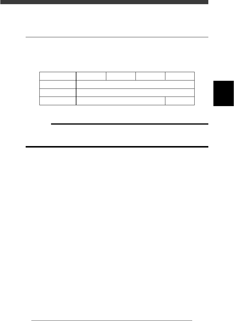
The YV180X surface mounter operates on the following power supply
specifications.
Power supply specifications
45801-C0-00
Power
Frequency
Power capacity
3-phase AC 200 / 208 / 220 / 240 / 380 / 400 / 416V ± 10%
50/60Hz
4.0KVA
YV100X YV88X YV100XT YV180X
6.0KVA
c
CAUTION
Before making connections, check that the primary tap terminals on the two transform-
ers are correctly connected to match the voltage you are using. A label showing
connection diagrams is affixed to the inner side of the rear cover of the machine.
8
-4
Service Manual
Chapter 8
SED8013110
8
Power and machine connections
1.2 Power connections
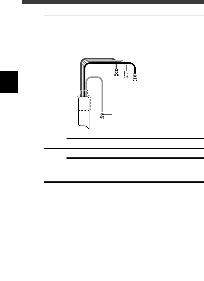
Use a power supply cable shown below, and connect each wire of the cable
to the primary side terminals L1, L2 and L3 of the main breaker QF11
which is located on the lower left of the machine as you face the rear of the
machine, and also to the ground terminal on the frame.
Power supply cable example (4-conductor cabtyre cable)
43801-C0-00
L1
L2
L3
Ground
Green
L=350mm
L=350mm
Round crimp terminal 3.5-4
Y crimp terminal with
insulation tube
TMEV3.5-Y5
c
CAUTION
Use a power supply cable with a conductor wire cross section of at least 3.5mm
2
.
w
WARNING
ENSURE THAT THE POWER SUPPLY IS OFF BEFORE CONNECTING THE
POWER SUPPLY CABLE, TO AVOID THE RISK OF ELECTRICAL SHOCK.
ALSO MAKE CERTAIN THAT THE GROUND CABLE IS PROPERLY
CONNECTED TO THE MACHINE.