YV180X_Mainte_E.pdf - 第128页
4 -70 Service Manual Chapter 4 SED8013110 4 Machine adjust mode q Quit the calibration according to the message displayed on the operation monitor . T o calibrate other heads, repeat from Step 4. w Save the calibrated da…
4
-69
SED8013110
Service Manual
Chapter 4
4
Machine adjust mode
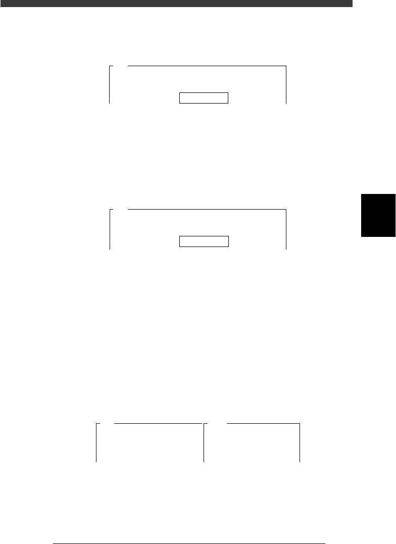
5 Enter the component database No. and press the [ENTER]
key.
Enter here the database number of the component you have prepared.
47455-C0-00
Please input the database number which has already
prepared . . .
Database No. 766
A461
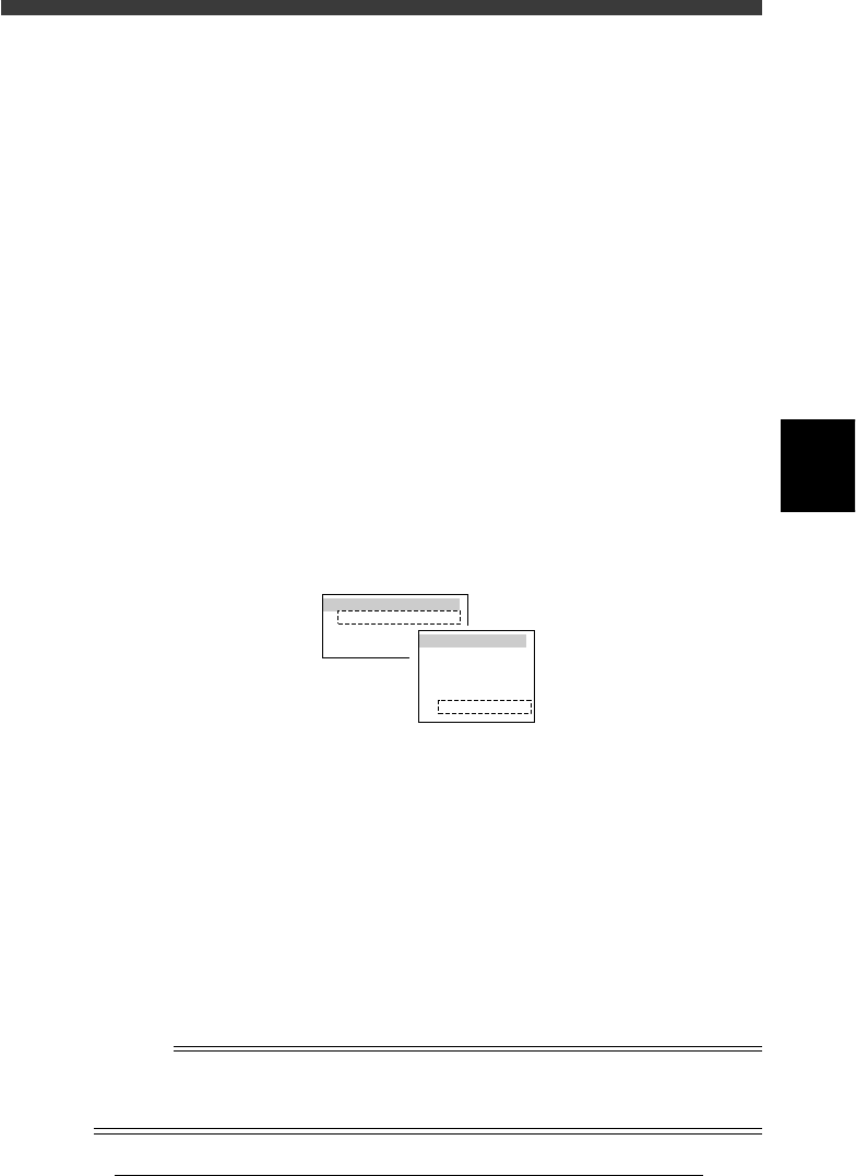
6 Follow the message to continue adjustment.
When the component you specified in Step 5 is registered as a tray
component, press the [ENTER] key to proceed to the next step. If it is
registered as a tape feeder component, the feeder set No. input box
appears as shown below. Enter the feeder set No. where you installed the
tape feeder and press the [ENTER] key. (In this case, the component is
automatically picked up, so Steps 8 and 9 are skipped.)
47456-C0-00
The specified component uses a tape feeder. It will be
picked up........
Feeder Set No. 20
A462
7 Check safety, then press the [ENTER] key again.
The head moves to the component pickup position.
e
8 Press the emergency stop button, and attach the compo-
nent by hand to the head.
Attach the component to the head you have specified in Step 4. When you
use a rectangular component, align the long side in parallel with the X-
axis.
9 Cancel emergency stop.
Release the emergency stop button and press the [READY] button.
0 Check safety, then press the [ENTER] key.
The head moves above the camera and the component is recognized at
each mounting angle. After calibration is complete, the results are
displayed on the right of the screen as shown below.
47457-C0-00
A481
Atable
<<<Result>>>
The results of adjusting the R-axis
Accuracy Table are....
Camera No.=5
Head.
1
0deg
0.000
180deg
0.000
90deg
0.000
-90deg
0.000

4
-70
Service Manual
Chapter 4
SED8013110
4
Machine adjust mode
q Quit the calibration according to the message displayed on
the operation monitor.
To calibrate other heads, repeat from Step 4.
w Save the calibrated data.
Select <B2 SAVE DATA> or <B0 SAVE & QUIT> and press the [ENTER]
key. (To quit without saving, select <B3 RECOVER ADJUST> or <B7
QUIT> and press the [ENTER] key.)
4
-71
SED8013110
Service Manual
Chapter 4
4
Machine adjust mode
4. Other commands
In addition to adjustment utilities, the following commands are also
available on the <B/SAVE & QUIT> menu in MCH_ADJUST mode to
save the adjusted data, recover previous data, or set the teaching condi-
tions.
3/3/B2 SAVE DATA
Saves the machine data into the file. (Adjusted data is temporarily stored in
the RAM of the controller before this command is run.) After the machine
data is stored with this command, the subsequent operations are controlled
by using this data.
3/3/B3 RECOVER ADJUST
Recovers and reloads the previous data stored in the file. The subsequent
operations are controlled by using the previous data stored in the file.
3/3/B4 CONDITION OF TCH
Use this command to select the unit and speed to perform teaching or
tracing.
47413-D8-00
TEACH-UNIT SEL.
Camera
Head1
Head8
SPEED SELECT.
Speed1 =
Speed2 =
Speed3 =
Speed4 =
Speed5 =
100
80
60
40
20
TEACH-UNIT SEL. (Teaching/trace unit selection):
Select the teaching/trace unit from among “Head 1”,
“Head 8“ or “Camera”. Selecting “Camera” allows
you to perform teaching or tracing while viewing
the target on the vision monitor.
SPEED SELECT (Axis moving speed selection):
Select the speed from among “Speed 1” to “Speed
5” to perform teaching or tracing. “100” is the
highest speed. For safety, a lower speed is recom-
mended during adjustment. The speed settings
(SPEED 1 to 5) can be changed with the <3/4/B2
RUNNING SPEED> command.
Reference
This command can also be run by pressing the [F10] or [F9] key on the data edit screen
such as the Position (machine coordinates) screen. For details on teaching and tracing,
refer to the mounter operation manual.