YV180X_Mainte_E.pdf - 第62页
4 -4 Service Manual Chapter 4 SED8013110 4 Machine adjust mode 2. Utility <3/3/A> The Utility menu has commands frequently used during adjustment. T o run a command, move the cursor to the command and pr ess the [E…
4
-3
SED8013110
Service Manual
Chapter 4
4
Machine adjust mode
1.
Machine adjust mode main menus
Adjustment commands and utilities are stored in Machine Adjust mode.
When you select <3/3/ MCH_ ADJUST>, the two command menu win-
dows <A/UTILITY> and <B/SAVE & QUIT> can be selected. This
chapter explains these command menus. You can also refer to the help
message as necessary for information about each command, which appears
on the operation monitor by pressing the [F1] key.
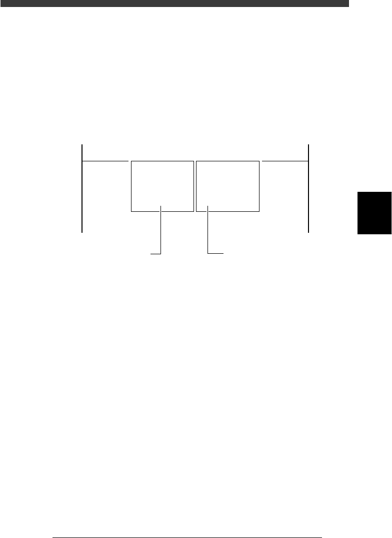
Main menu windows in Machine Adjust mode
47401-C0-00
<<<APPLICATION>>> 3/MAINTE/M
<<MODE>> 3/MCH_ADJUST
<COMMAND_LIST> A/UTILITY B/SAVE & QUIT
A1 VACUUM ON
A2 VACCUM OFF
A3 PICK COMPONENT
A4 DUMP COMPONENT
A5 CHANGE NOZZLE
A6 HEAD DOWN VALVE
A7 CHANGE SPEED
A8 SEARCH ORIGIN
B1 ADJUST TARGET
B2 SAVE DATA
B3 RECOVER ADJUST
B4 CONDITION OF TCH
B5 *
B6 **
B7 QUIT
B0 SAVE & QUIT
This menu opens when
<B/SAVE & QUIT> is selected.
This menu opens when
<A/UTILITY> is selected.
4
-4
Service Manual
Chapter 4
SED8013110
4
Machine adjust mode
2. Utility
<3/3/A>
The Utility menu has commands frequently used during adjustment. To run
a command, move the cursor to the command and press the [ENTER] key
or directly enter the corresponding number. The function of each command
is explained below.
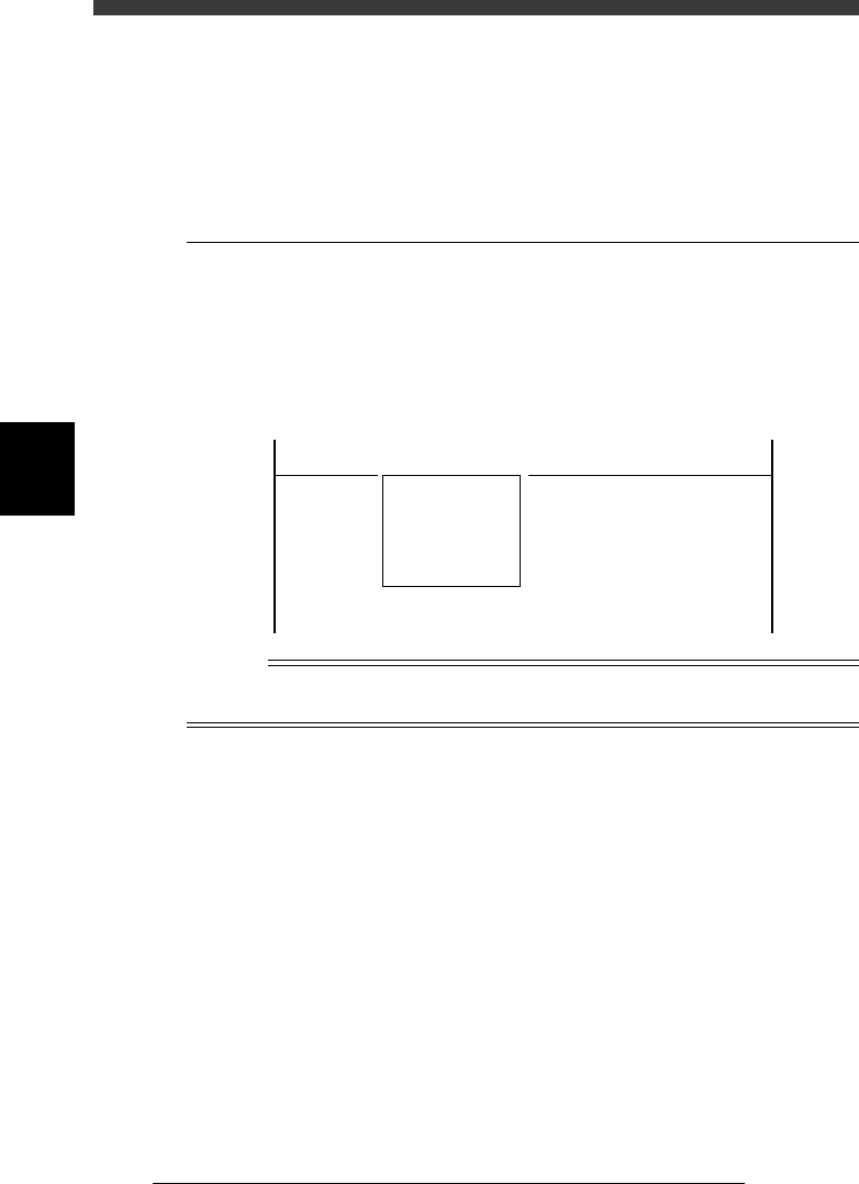
2.1 Vacuum ON/OFF
<3/3/A1> <3/3/A2>
Selecting <3/3/A1 VACUUM ON> generates the vacuum in all heads. Use
this command when picking up a component with a nozzle during adjust-
ment. (You cannot turn on a particular nozzle with this commnand.)
To stop the vacuum generation, select <3/3/A2 VACUUM OFF>.
VACUUM ON/OFF commands
47402-C0-00
<<<APPLICATION>>> 3/MAINTE/M
<<MODE>> 3/MCH_ADJUST
<COMMAND_LIST> A/UTILITY
A1 VACCUM ON
A2 VACCUM OFF
Reference
To generate vacuum for a particular nozzle, use the <A1 INPUT/OUTPUT MONITOR> or
<A4 VACUUM IN MONITOR> command in MANUAL mode.

4
-5
SED8013110
Service Manual
Chapter 4
4
Machine adjust mode
2.2 Pickup component
<3/3/A3>
Use this command when you want to check the component pickup position
or pickup function. For example, you can check if the feeder set positions
on the feeder plate are correctly adjusted, by picking up a component from
the feeder with this command. The following steps explain the procedure
for component pickup test. Prepare in advance, a tape feeder with compo-
nents to be tested.
1 Run the component pickup test.
Select <3/3/A3 PICK COMPONENT> - “A table” (or “B table”) and press
the [ENTER] key.
47403-D8-00
Database No. 1
Head No. 1
A461
Please input the data base number which has already
prepared.
After input, please press the [ENTER] key.
table
A table
B table
A463
It will pick one component.
An nozzle type used by this is Type 11
Please input the head number.
<<<APPLICATION>>> 3/MAINTE/M
<<MODE>> 3/MCH_ADJUST
<COMMAND_LIST> A/UTILITY
A3 PICK COMPONENT
Step
3
Step
2
Step 1
2 Enter the database No. of the component and press the
[ENTER] key.
3 Enter the head No. and press the [ENTER] key.
Specify the head No. for which you want to perform the component
pickup test.
4 Enter the feeder set No. and press the [ENTER] key.
Specify the feeder set No. at which you have installed the tape feeder for
the component pickup test.
47404-D8-00
Feeder Set No. 10
A462
As a Tape feeder is specified by this component,
the machine can pick component automatically.
Please type feeder position number.