YV180X_Mainte_E.pdf - 第139页
5 -10 Service Manual Chapter 5 SED8013110 5 Manual mode 3.5 Exit fr om manual <3/4/B0> Run the <3/4/B0 EXIT FROM MANUAL> command to exit MANUAL mode. EXIT FROM MANUAL command 47513-C0-00 <<<APPLICATI…
5
-9
SED8013110
Service Manual
Chapter 5
5
Manual mode
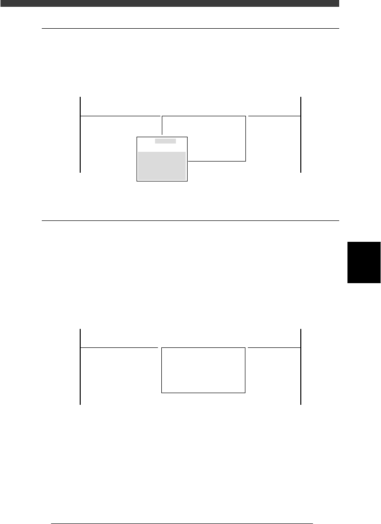
3.3 Point move
<3/4/B3>
When you run <3/4/B3 POINT MOVER>, the submenu box appears for
specifying the position where you want to move the unit selected with the
<3/4/B1 SELECT SERVO MOTOR> command.
Position input box
47511-C0-00
Edit coordinates of
A_table XY
Cursor key to select
[Enert] key to move
[ESC] key to abort
<<<APPLICATION>>> 3/MAINTE/M
<<MODE>> 4/MANUAL
<COMMAND_LIST> A/IO_UTILITY B/SERVO_CONTROL
B3 POINT MOVE
0.000
0.000
3.4 Initialize servo origin
<3/4/B6>
Run the <3/4/B6 INIT. SERVO ORIGIN> command to perform return-to-
origin. Servo-controlled units on all axes move to their origins. You must
perform return-to-origin at least once after the power is turned on.
If you want to reperform return-to-origin, press the [SHIFT]+[ENTER]
keys. In this case, the machine reference of each axis is also displayed
when return-to-origin is complete. (See 2.7 in chapter 4.)
INIT. SERVO ORIGIN command
47512-C0-00
<<<APPLICATION>>> 3/MAINTE/M
<<MODE>> 4/MANUAL
<COMMAND_LIST> A/IO_UTILITY B/SERVO_CONTROL
B6 INIT. SERVO ORIGIN

5
-10
Service Manual
Chapter 5
SED8013110
5
Manual mode
3.5 Exit from manual
<3/4/B0>
Run the <3/4/B0 EXIT FROM MANUAL> command to exit MANUAL
mode.
EXIT FROM MANUAL command
47513-C0-00
<<<APPLICATION>>> 3/MAINTE/M
<<MODE>> 4/MANUAL
<COMMAND_LIST> A/IO_UTILITY B/SERVO_CONTROL
B0 EXIT FROM MANUAL

Chapter 6
Conveyor unit and air supply
unit adjustment
This chapter explains how to adjust the conveyor units used to
transfer and clamp PCBs, and also how to set the optimum air
pressure for pneumatic-driven units.
1. Adjusting the conveyor unit 6-3
1.1 Adjusting the air valve................................................................................6-4
1.2 Conveyor speed .........................................................................................6-6
1.3 Adjusting the conveyor belt tension ...........................................................6-9
1.4 Adjusting the W-axis initial position .........................................................6-10
1.5 Y-axis (A/B table) initial position............................................................... 6-11
1.6 PCB detection sensors ..............................................................................6-13
2. Air supply unit 6-16
2.1 Air pressure regulator ...............................................................................6-16
2.2 Pressure-drop detection level ...................................................................6-17