YV180X_Mainte_E.pdf - 第166页
7 -12 Service Manual Chapter 7 SED8013110 7 T roubleshooting 6. FNC nozzles 45710-D8-00 Symptom The flying nozzle position cannot be detected. The specified nozzle is not ready for operation. The flying nozzle cannot be …
7
-11
SED8013110
Service Manual
Chapter 7
7
Troubleshooting
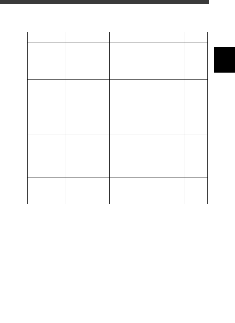
5. Feeder
45709-C0-00
Symptom
Components
are not fed
properly and
pickup errors
frequently
occur.
Multi-stick
feeders do not
function.
Pickup error
frequently
occurs with
multi-stick
feeders.
Pickup position
error occurs.
Corrective action
Correct the supply pitch for the
feeder by loosening the screws at
the air cylinder and fitting them in
the proper position.
Check that the air and power are
supplied. Set the changeover switch
to the "center" position. Also check
that the position of the positioning
pin is matched with the feeder set
No. in the Component Information.
Adjust the ascent and descent speed
to increase the speed for supplying
components. Also, check the pickup
position and correct it if necessary.
Detach the feeder from the feeder
plate and remove dust and debris.
Refer to
Feeder
user's
manual
Feeder
user's
manual
Feeder
user's
manual
Feeder
user's
manual
Possible cause
The feeder's supply
pitch is not correct.
There is a problem
with air supply,
power supply,
changeover switch,
or feeder
installation position.
Component supply
does not match the
timing that the head
picks up
components, or the
pickup position is
not correct.
Dust or debris has
intruded between
the feeder plate and
the feeder.
7
-12
Service Manual
Chapter 7
SED8013110
7
Troubleshooting
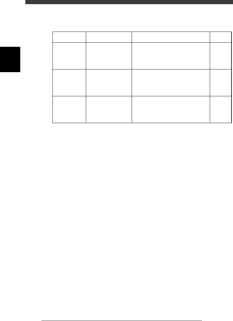
6. FNC nozzles
45710-D8-00
Symptom
The flying
nozzle position
cannot be
detected.
The specified
nozzle is not
ready for
operation.
The flying
nozzle cannot
be clamped.
Possible cause
The R-axis coordinate
for the ‘Wait point”
on the Position screen
is incorrect.
A nozzle not designed
for flying nozzle
change was selected.
The R-axis coordinate
for the ‘Wait point”
on the Position screen
is incorrect.
Corrective action
Set the R-axis coordinate of the
“Wait point” to the correct value.
Check the head No. and nozzle type
No. on the <3/1/A8 FLYING
<NOZZLE INF.> screen.
Set the R-axis coordinate of the
“Wait point” to the correct value.
Refer to
3.2 in
Chapter 4
2.6 in
Chapter 2
3.2 in
Chapter 4
7
-13
SED8013110
Service Manual
Chapter 7
7
Troubleshooting
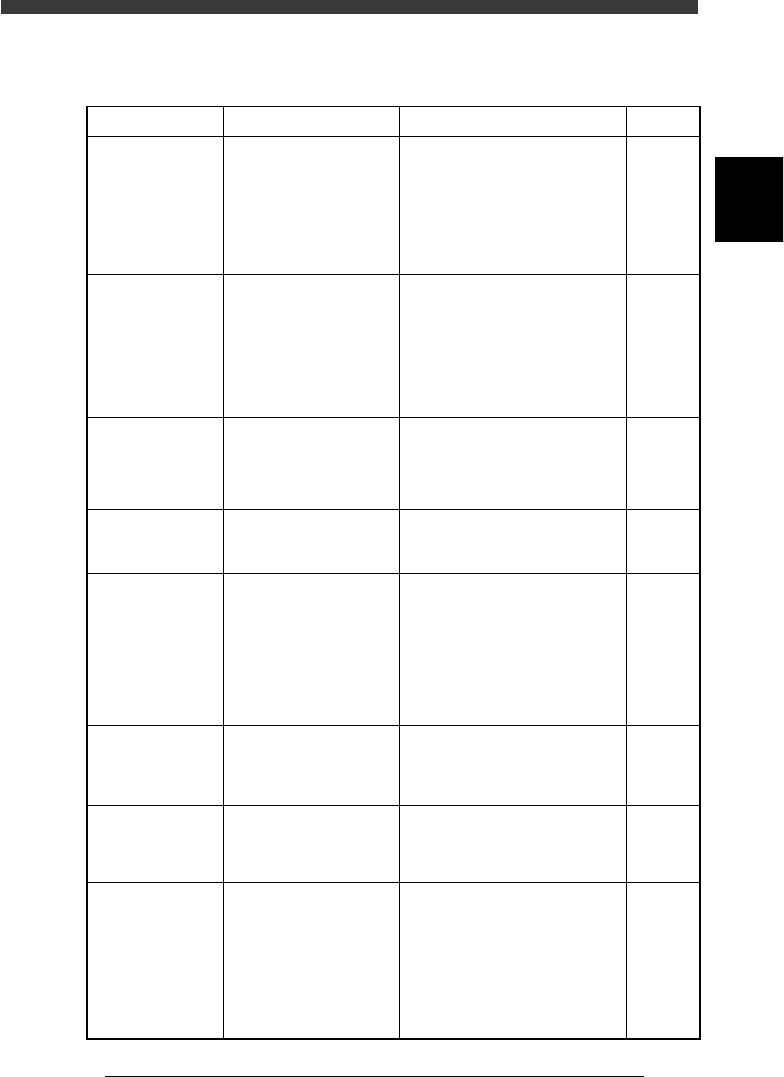
7. Others
45711-C0-00
Symptom
You increased the
number of retries
in the component
information, but
that number of
retries was not
performed.
PCB data error (for
example, "Pickup
position ...") occurs
when PCB data is
loaded.
PCB data error (for
example, "Mount
position ...") occurs
when PCB data is
loaded.
Numeric keypad
on the keyboard
does not function.
When the [ENTER]
key on the
keyboard is
pressed to create
or edit data, the
cursor does not
move to the right
but moves down to
the lower line.
The number of
mount data points
resulted in error.
An interlock error
has occurred.
Sensor errors have
occurred.
Corrective action
It is not possible to perform retries
at a number of times exceeding the
Retry Limit setting on the Position
screen in MCH_DATA mode. Set
the number of retries in the
component information, which is
less than the retry setting on the
Position screen.
Check the pickup position and
make corrections as needed.
Check for the PCB origin and block
repeat data, as well as mount
position data.
Press the NUMLOCK key at the
upper right of the keyboard, and
check that its LED turns on.
Release the CAPSLOCK key.
Check the mount information data,
block repeat data, local fiducial data
and local bad mark data, then
reduce the number of data points.
Raise the head by hand to a height
where no interference occurs.
Check the head decent air valve for
piston movement inside it or the
nozzle shaft for deformation. Check
the “Pick Height” and “Mount
Height” values and correct them if
necessary. Check also the lower end
sensor position and correct it if
necessary.
Possible cause
The number of retries you
set in the component
information is more than
the retry setting on the
Position screen in
MCH_DATA mode.
The Pos. Definition of the
BASIC INFO. parameters
in the component
information was set to
"Teaching", and a value
exceeding the software
limit is entered in the
Feeder Pos_X or Y.
The mount data is not
correct.
The NUMLOCK key is
unlocked.
The CAPSLOCK key is
locked.
There are too many mount
data points.
A head is positioned at a
height possibly causing the
nozzle tip to interfere with
other parts of the machine.
The vertical movement of a
head is abnormal. The
“Pick Height” or “Mount
Height” value of the PICK
& MOUNT INFO.
parameters is too large or
the position of the lower
end sensor in not
appropriate.
Refer to
3.2 in
Chapter 4
Mounter
operation
manual
Mounter
operation
manual
Mounter
operation
manual