YV180X_Mainte_E.pdf - 第162页
7 -8 Service Manual Chapter 7 SED8013110 7 T roubleshooting 3.2 QFP components 45706-D8-00 Possible cause The component information is incorrect. The direction for supplying the component is not correct. (If the supply d…
7
-7
SED8013110
Service Manual
Chapter 7
7
Troubleshooting
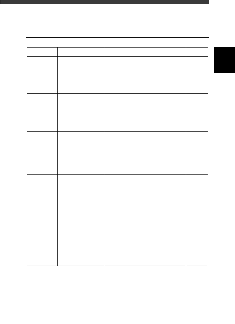
3. Recognition errors
3.1 Chip components
45705-D8-00
Refer to
Maintenance
guide
(Basic)
Feeder
user's
manual
Chapter 2
Mounter
operation
manual
Corrective action
Wipe the lens surface and half mirror
with a lens cleaner.
If the pickup position has deviated from
the center of the component, the nozzle
tends to pick up the component by the
edge, so check the tape feeder for
operation and installation on the feeder
plate.
Generate a negative pressure for all
heads in MANUAL mode, and press the
nozzles up by finger to check the spring
action. If the nozzle does not return
smoothly, then lubricate. Clean away
dirt or debris from the nozzle as
necessary.
If the SHAPE INFO. parameters are
incorrect, the component cannot be
recognized. Enter correct values for
these parameters.
Similarly, if the component is supplied
in the wrong direction, this also results
in recognition errors. The "Pick Angle
deg" (used for component recognition
reference) of the PICK & MOUNT
INFO. parameters in the component
database is specified as 0°, assuming
that components are supplied in the
horizontally long loading position. So, if
the components are supplied in a
vertically long loading position, set
"Pick Angle deg" to 90° (or -90°).
Possible cause
Dust or dirt is on the
camera lens.
The nozzle is picking
up the component by
the edge.
The spring-action of
the nozzle does not
move smoothly, or dirt
or debris adheres to the
nozzle tip.
The SHAPE INFO.
parameters in the
component information
are incorrect, or the
component is supplied
in the wrong loading
position with respect to
the pickup angle
setting.
Symptom
Recognition
errors
frequently
occur with
almost all
components.
Recognition
errors
frequently
occur with a
specific
component.
Recognition
errors
frequently
occur with a
specific
head.
Specific
components
cannot be
recognized.
7
-8
Service Manual
Chapter 7
SED8013110
7
Troubleshooting
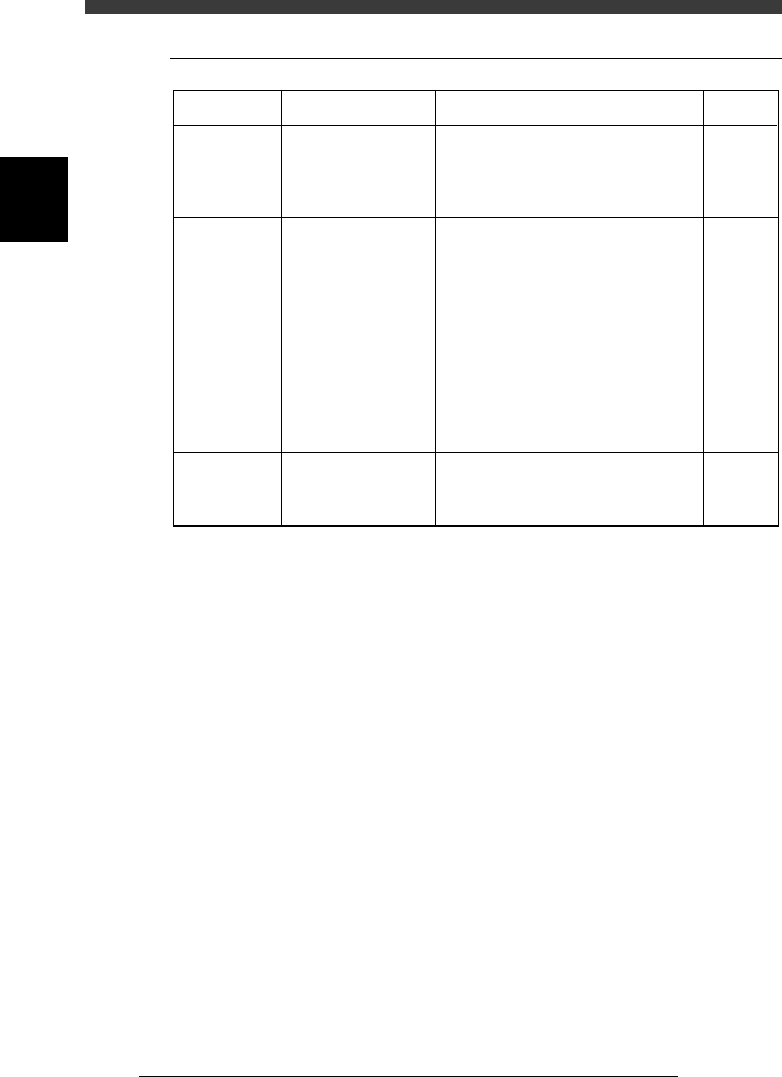
3.2 QFP components
45706-D8-00
Possible cause
The component
information is
incorrect.
The direction for
supplying the
component is not
correct. (If the supply
direction is wrong,
the number of leads
is reversed between
the length and width
sides, causing a
recognition error
even if the SHAPE
data is correct.)
The vision camera
light selection is
incorrect.
Corrective action
Check the parameter settings in the
component information, and perform
the "PARAM. SEARCH" command
in the Adjust Assistant mode.
The "Pick Angle deg" (used for
component recognition reference) of
the PICK & MOUNT INFO.
parameters in the component database
is specified as 0°, assuming that
components are supplied in the
horizontally long loading position. So,
if the components are supplied in a
vertically long loading position, set
"Pick Angle deg" in the component
information to 90° (or -90°).
Check that "Lighting Selection" of the
VISION INFO. parameters is set to
"Main + Coax".
Symptom
Recognition
errors
frequently
occur.
Components
cannot be
recognized.
Refer to
Mounter
operation
manual
Mounter
operation
manual
7
-9
SED8013110
Service Manual
Chapter 7
7
Troubleshooting
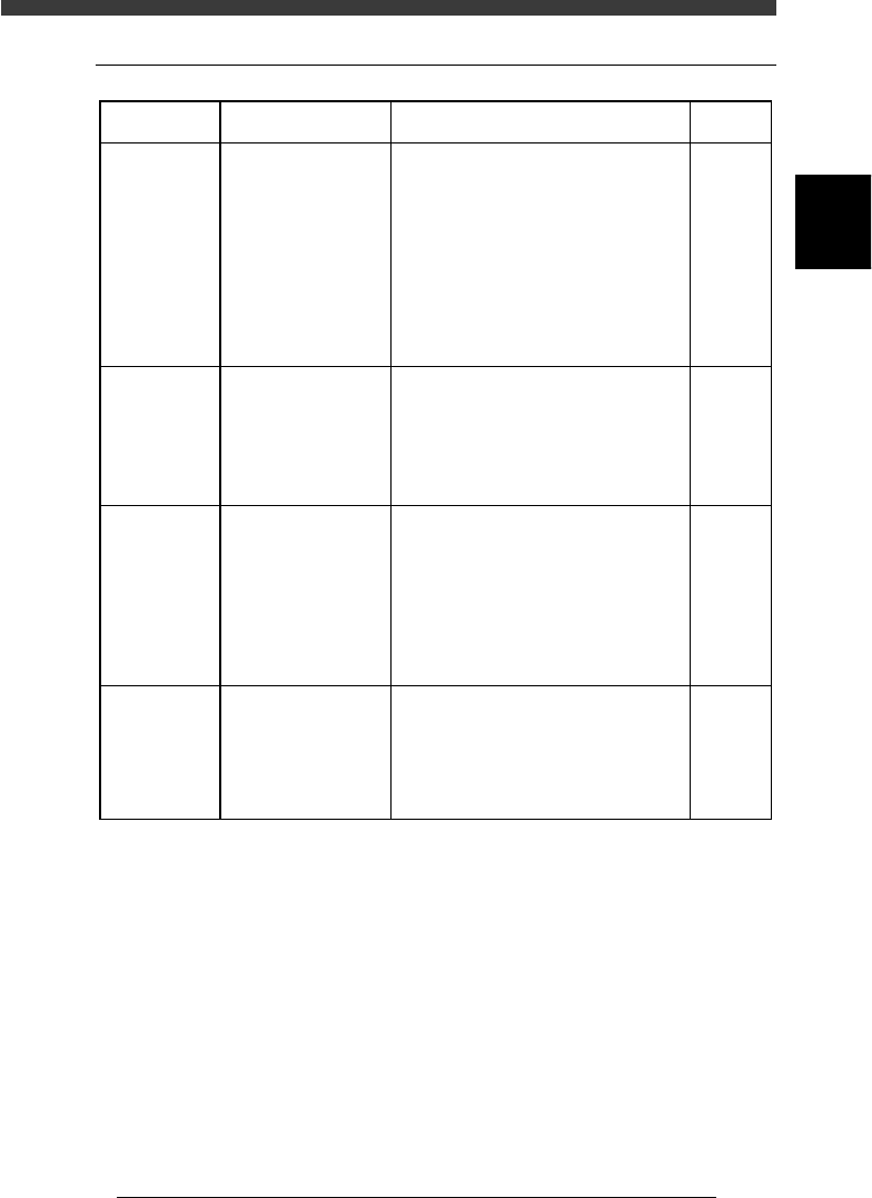
3.3 Mark
45707-C0-00
Symptom
Fiducial mark
cannot be
recognized.
Fiducial mark
recognition is
not reliable.
In FINE
mode, the
recognition
position
cannot
converge on
the specified
point.
Fiducial mark
recognition is
not reliable.
Possible cause
The PCB is not
clamped securely, or
the mark information
data is incorrect, or
the mark shape or
size is outside the
specifications.
A solder leveler mark
or low-contrast mark
cannot be recognized
reliably.
The convergence
conditions are too
tight.
The FIDUCIAL SEL
option was set to
"NotUse" when
setting teaching
Corrective action
Check that the PCB is clamped securely
. If no problem, check the mark data
and optimize the threshold level with
the "PRAM. SEARCH" command in
the Adjust Assistant mode so that the
mark can be clearly viewed. If there is
any noise around the mark, narrow the
mark search area or cut the noise by
adjusting the Cut Outer Noise
parameter in the mark information.
Readjust the moving camera lighting in
the mark information, then optimize the
threshold level with the "PRAM.
SEARCH" command in the Adjust
Assistant mode so that the mark can be
clearly viewed.
Relieve the convergence conditions in
MCH_DATA mode or set the
"Algorithm Type" of the Vision Info.
parameters to "Normal".
Set the FIDUCIAL SEL option to
"Use" when setting teaching conditions,
then reperform fiducial mark
recognition.
Refer to
Mounter
operation
manual
Mounter
operation
manual