YV180X_Mainte_E.pdf - 第148页
6 -10 Service Manual Chapter 6 SED8013110 6 Conveyor unit and air supply unit adjustment 1.4 Adjusting the W -axis initial position The W -axis initial position is the distance expressed as a minus value between the con …
6
-9
SED8013110
Service Manual
Chapter 6
6
Conveyor unit and air supply unit adjustment
1.3 Adjusting the conveyor belt tension
The carry-in and carry-out conveyors move by belt drive to transfer PCBs.
If the conveyor belts are too loose, they may slip on the pulleys causing
unstable transfer. If the belts are too tight, they may wear excessively or
break. The tension of each belt on the fixed and movable rails should be
adjusted evenly. If necessary, adjust the tension as follows.
e
1 Press the emergency stop button.
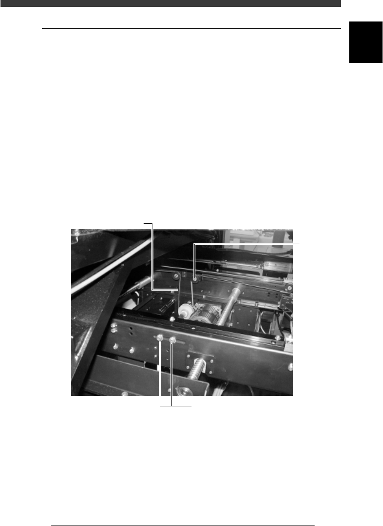
2 Loosen the tension adjusting bolts.
The tension adjusting bolts are located on the side of the W-axis ball screw
of the carry-in and carry-out conveyors and used to secure the idler stay.
Use a hex wrench to loosen the bolts (but do not remove them).
3 Adjust the belt tension.
Slide the tension adjusting bolts (the idler stay) towards the outer or inner
side of the machine to adjust the tension.
Adjustment of conveyor belt tension
43612-D8-00
Conveyor belt
Idle
r
Tension adjusting bolts
4 Retighten the tension adjusting bolt.
Check the tension by hand, then run the conveyor belt and check that the
motor pulley does not slip.
6
-10
Service Manual
Chapter 6
SED8013110
6
Conveyor unit and air supply unit adjustment
1.4 Adjusting the W-axis initial position
The W-axis initial position is the distance expressed as a minus value
between the conveyor rails when the W-axis is in the return-to-origin
position. To set the W-axis initial position, follow these steps.
1 Perform return-to-origin.
e
2 Press the emergency stop button and determine the initial
position.
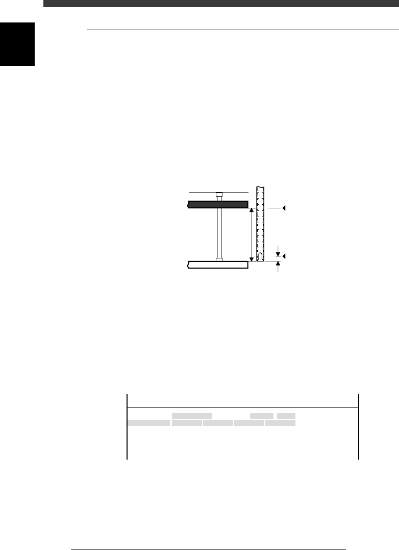
Measure the conveyor width W (distance between the fixed rail and the
movable rail). Subtract 0.5mm from the width W as a clearance margin,
and then prefix a “minus” sign to this value. This value is the W-axis initial
position.
Conveyor width measurement and initial position
43604-D8-00
1 2 3 4 5
0.5
W
Origin
Fixed conveyor rail
Movable conveyor rail
Initial position = - (W - 0.5
)
3 Open the software limit screen and enter the initial
position.
1. Select <3/3/B1 ADJUST TARGET> − ”Soft. Limit” and press the [ENTER]
key.
2. Use the arrow keys to line up the cursor with “Init.Pos” of the conveyor
whose width you measured in Step 2 (for example, W1).
3. Use the number keys to enter the initial position value obtained in Step
2.
W-axis initial position setting screen
47604-D8-00
Axis
W1/RIGHT
W2/A-TBL
W3/B-TBL
W4/LEFT
+direct.
11.323
13.753
11.993
7.113
OBJECT
Software Limit
TCH.UNIT SPEED
- - - - - - - -
-direct.
-277.973
-272.227
-274.202
-283.200
Inir.Pos
-323.600
-321.790
-323.650
-328.650
Init.Mov
<<<APPLICATION>>> 3/MAINTE/M
<<MODE>> 3/MCH_ADJUST
4 Adjust the initial positions of other conveyor widths in the
same way.
5 Save the settings.
Press the [ESC] key, then select <B2 SAVE DATA> or <B0 SAVE & QUIT>
and press the [ENTER] key. (To quit without saving, select <B3 RECOVER
ADJUST> or <B7 QUIT> and press the [ENTER] key.
6
-11
SED8013110
Service Manual
Chapter 6
6
Conveyor unit and air supply unit adjustment
1.5 Y-axis (A/B table) initial position
For smooth PCB transfer, the carry-in conveyor, A/B tables and carry-out
conveyor must be aligned straight. To ensure this, the initial position of the
Y-axis (A/B tables) is specified on the Soft Limit screen. If resetting
becomes necessary, use the following procedure.
1 Perform return-to-origin.
e
2 Press the emergency stop button.
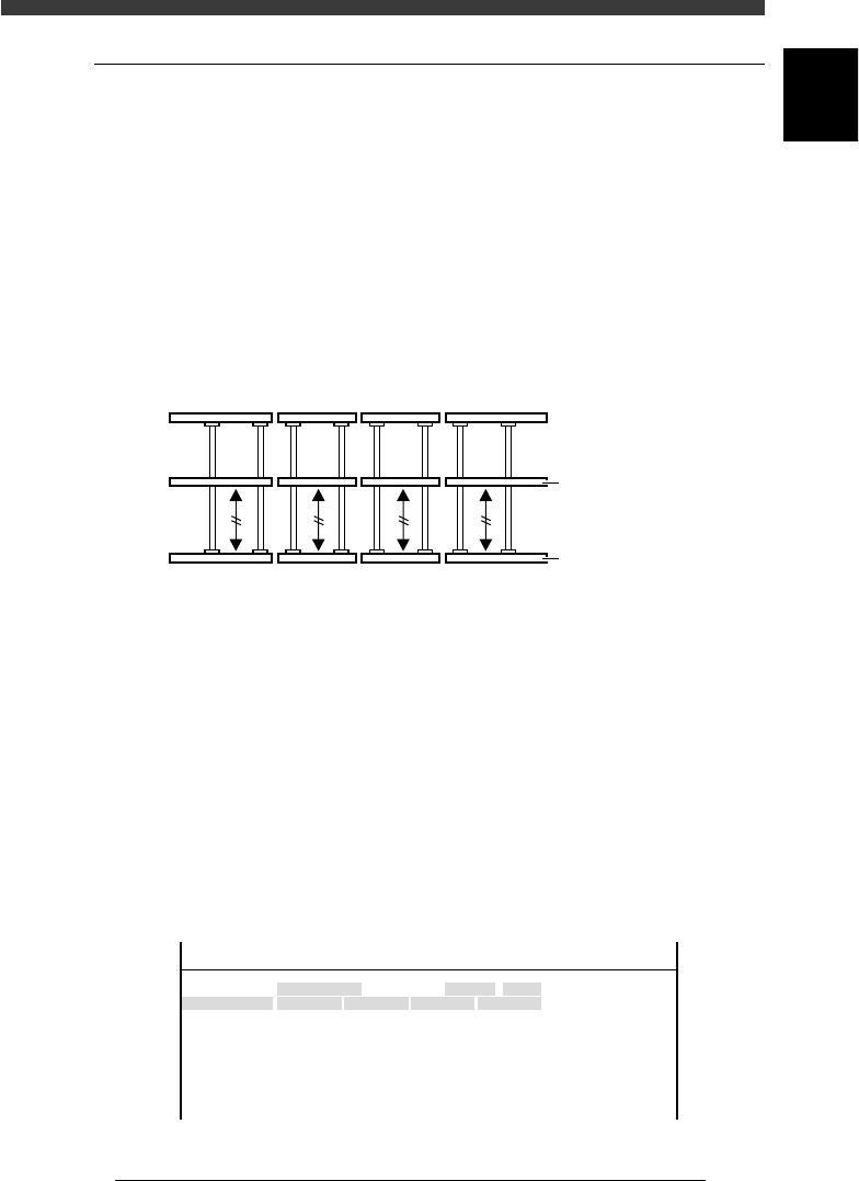
3 Align the conveyor rails.
Move the A and B tables by hand to align them with the carry-in and
carry-out conveyors, so that the fixed conveyor rails are all lined up
straight.
Conveyor rails during PCB transfer
43609-D8-00
Movable conveyor rai
l
Fixed conveyor rail
4 Open the software limit screen.
Select <3/3/B1 ADJUST TARGET> - ”Soft. Limit” and press the [ENTER]
key.
5 Enter the Y-axis initial positions.
1. Use the arrow keys to line up the cursor with “Init.Pos” in the “Y1/A-
TBL” row.
2. Press the [F10] key and set the teaching conditions.
Select any teaching unit and speed in this case.
3. Press the [F10] key twice to enter the Y1-axis initial position.
4. Next, move the cursor to “Init.Pos” in the “Y1/B-TBL” row and press the
[F10] key twice to enter the Y2-axis initial position.
Y-axis initial position setting
47607-D8-00
Axis
Y1/A-TBL
Y2/B-TBL
+direct.
452.790
449.199
OBJECT
Software Limit
TCH.UNIT SPEED
- - - - - - - -
-direct.
-26.815
-36.140
Inir.Pos
-25.815
448.199
Init.Mov
<<<APPLICATION>>> 3/MAINTE/M
<<MODE>> 3/MCH_ADJUST