YV180X_Mainte_E.pdf - 第36页
2 -17 SED8013110 Service Manual Chapter 2 2 Machine configuration mode 2.10 Feeder spec infor mation <3/1/B3> When <3/1/B4 FEEDER SPEC INF .> is selected, the submenu box appears for selecting “ FEEDER SPEC C…
2
-16
Service Manual
Chapter 2
SED8013110
2
Machine configuration mode
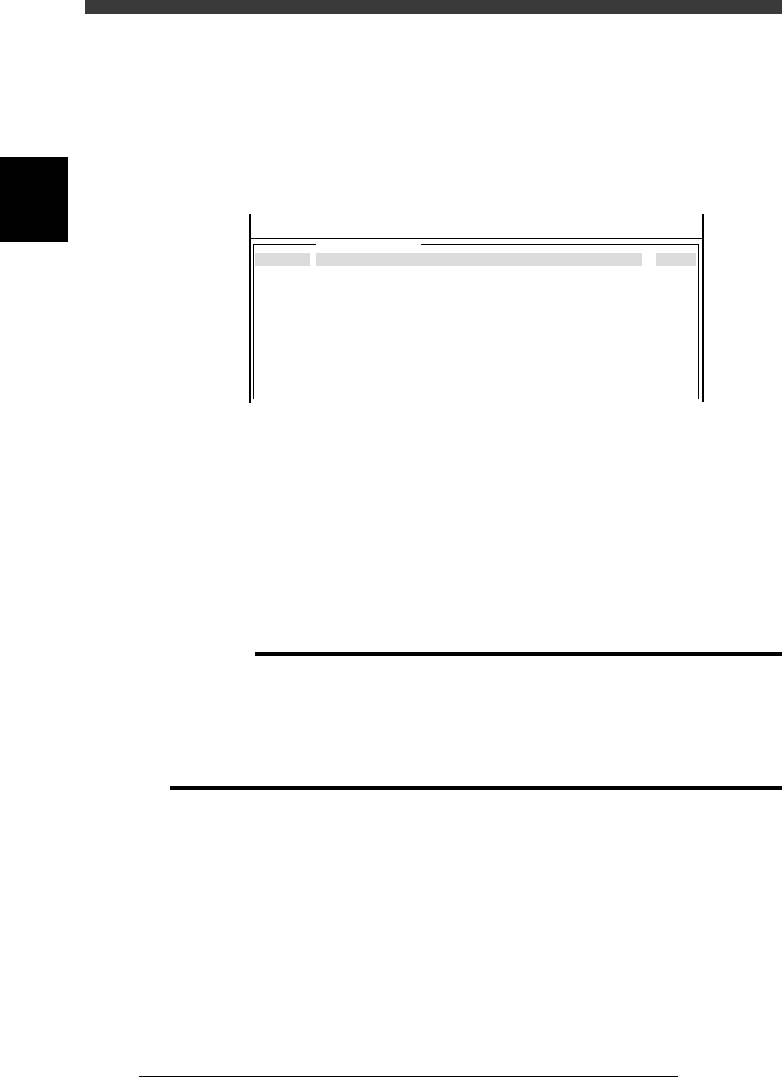
2.9.2 Nozzle spec type information
The nozzle spec type information shows component types that can be
picked up by each nozzle. Digit “0” means the component can be picked up
and code “-” means it cannot be picked up.
Nozzle spec type information
47213-C0-00
For1005Chp71
Component
<<<APPLICATION>>> 3/MAINTE/M
<<MODE>> 1/MCH_CONFIG
1234
0----------------------------------------------------------
-000---00----0---------------------------------------------
----000---00--00-----0-------------------------------------
------------0---000---00-----------------------------------
-----------------------------------------------------------
---------0-------------------------------------------------
-----------------------------------------------------------
-----------------------------------------------------------
-----------------------------------------------------------
-----------------------------------------------------------
-----------------------------------------------------------
Buffing
Use
Use
Use
NotUse
NotUse
NotUse
NotUse
NotUse
NotUse
NotUse
NotUse
Nozzle
TYPE- 71
TYPE- 72
TYPE- 73
TYPE- 74
TYPE- 75
TYPE- 76
TYPE- 77
TYPE- 78
TYPE- 79
TYPE- 7A
TYPE- 7B
5
Component Component types are horizontally listed in order.
The name of the component being selected appears
on the top line, together with the nozzle type.
“0”: can be picked up, “-”: cannot be picked up
Add Blow Specifies whether to perform air blow to prevent the
nozzle from taking a component back without
mounting it.
Buffing Specifies whether the nozzle uses spring action or
not.
c
CAUTION
Do not specify two or more nozzle types as “0” for the same component. Otherwise, the
machine may not operate correctly.
YAMAHA standard nozzles for the YV180X are specified as Type 71 to Type 79. If a
custom nozzle is used, it should be specified from Type 7A to Type 7Q, and the name
“Sp. NozzleA” to “Sp. NozzleF“ , which is the “component/nozzle” name shown on the
top line, should be specified in the component information.
2
-17
SED8013110
Service Manual
Chapter 2
2
Machine configuration mode
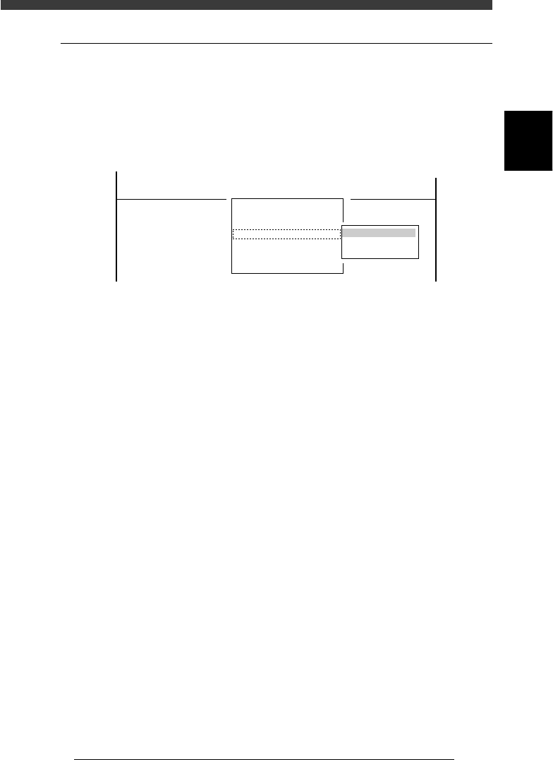
2.10 Feeder spec information
<3/1/B3>
When <3/1/B4 FEEDER SPEC INF.> is selected, the submenu box appears
for selecting “FEEDER SPEC CMN. (feeder spec common) information”
and “FEEDER SPEC TYP. (feeder spec type) information”. Each item on
this submenu is explained below.
Feeder spec information submenu
47214-C0-00
B1 HEAD SPEC. INF.
B2 FEEDER PLATE SPEC INF.
B3 NOZZLE SPEC INF.
B4 FEEDER SPEC INF.
B5
B6 DISPENSE SEQ. INF.
B7 DISPENSE COR. INF.
B0 EXIT
FEEDER SPEC
FEEDER SPEC CMN.
FEEDER SPEC TYP.
<<<APPLICATION>>> 3/MAINTE/M
<<MODE>> 1/MCH_CONFIG
<COMMAND_LIST> B/SPEC_INF
2
-18
Service Manual
Chapter 2
SED8013110
2
Machine configuration mode
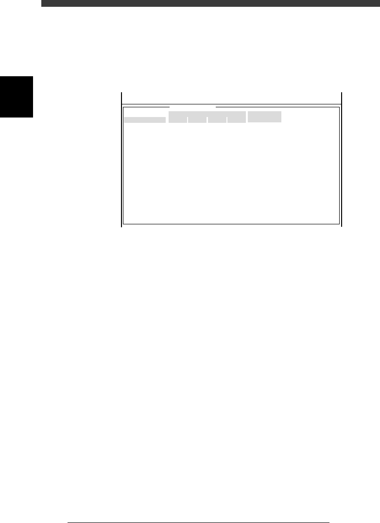
2.10.1 Feeder spec common information
The feeder spec common information shows specifications of feeders
including the size and drive sequence.
Feeder spec common information
47215-C0-00
FeederType
8mmTape
8mm1005cmp
12mmEmboss
12mmLongPitch
16mmEmboss
24mmEmboss
32mmSticky
32mmEmboss
44mmEmboss
56mmEmboss
MultiStick
WideMultiStick
Fix. TF
Ext. TC
AutoTC
Tape-A
Tape-B
PNEUMATIC Type
Left
7.80
7.80
9.80
14.50
16.50
20.50
25.00
24.70
30.70
42.50
39.80
54.50
0.00
0.00
0.00
0.00
0.00
Right
8.00
8.00
10.60
11.80
13.80
17.80
23.90
23.10
29.10
35.10
87.00
103.00
0.00
0.00
0.00
0.00
0.00
XShift
0.00
0.00
0.00
0.00
0.00
0.00
0.00
0.00
0.00
0.00
0.00
0.00
0.00
0.00
0.00
0.00
0.00
ZShift
0.00
0.00
0.00
0.00
0.00
0.00
0.00
0.00
0.00
0.00
0.00
0.00
0.00
0.00
0.00
0.00
0.00
Feeder Size Information Sequence
Type
Paper, Emboss
1005SizeComp
Paper, Emboss
Paper, Emboss
Paper, Emboss
Paper, Emboss
Sticky-Tape
Paper, Emboss
Paper, Emboss
Paper, Emboss
Multi-Stick
Multi-Stick
Tray-Changer
Tray-Changer
Tray-Changer
Paper, Emboss
Paper, Emboss
<<<APPLICATION>>> 3/MAINTE/M
<<MODE>> 1/MCH_CONFIG
Left, Right Distance to the left (or right) edge of the feeder from
the center of the feeder installation hole (in millime-
ter).
XShift An X-direction positional shift of the feeder pickup
position relative to a standard 8mm tape feeder
pickup position. The left direction shift is specified
as minus, while the right direction shift as plus.
ZShift A Z-direction positional shift of the feeder pickup
position relative to a standard 8mm tape feeder
pickup position. The downward direction shift is
specified as plus.
Sequence Type Shows the drive sequence of each feeder. (Cannot
be changed.)