YV180X_Mainte_E.pdf - 第67页
4 -9 SED8013110 Service Manual Chapter 4 4 Machine adjust mode 2.7 Search origin <3/3/A8> The <3/3/A8 SEARCH ORIGIN> command returns each axis to its origin position. After power is turned on, return-to-origi…
4
-8
Service Manual
Chapter 4
SED8013110
4
Machine adjust mode
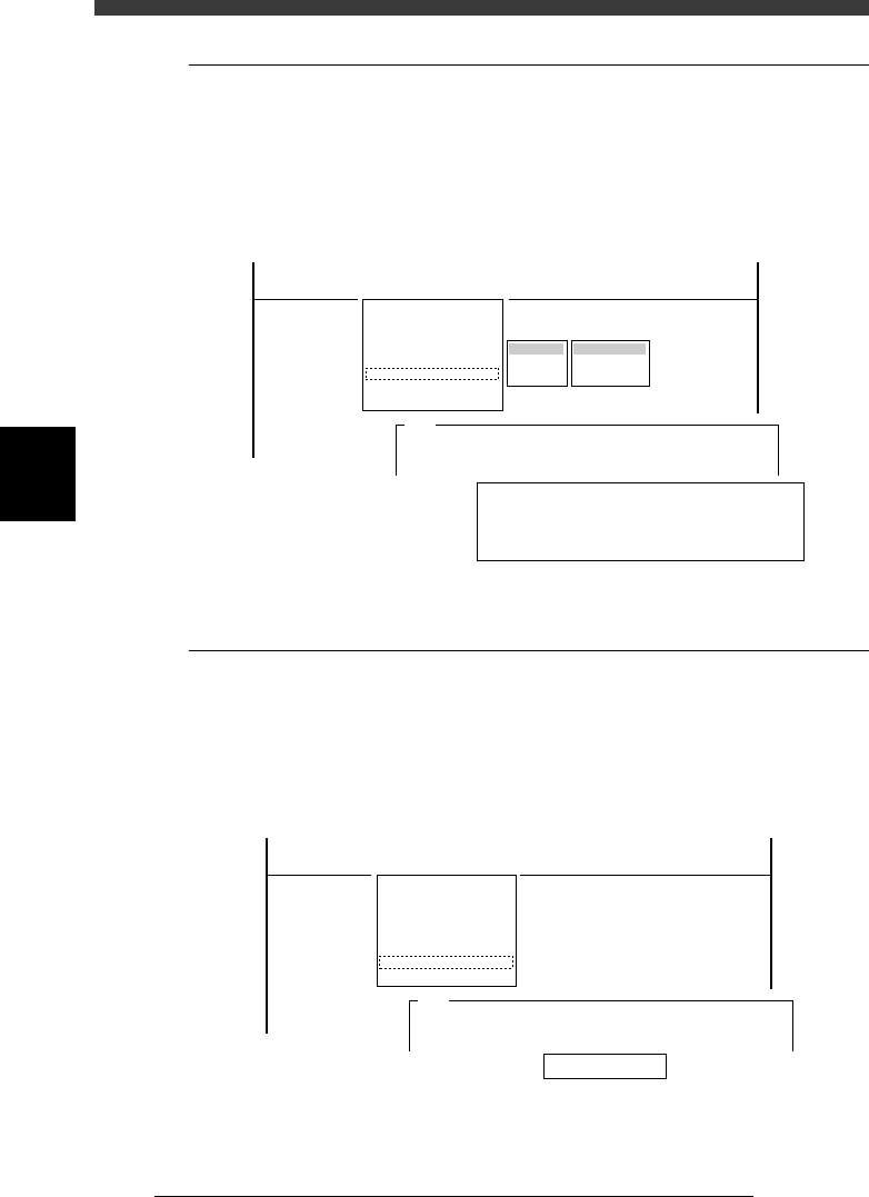
2.5 Head down valve
<3/3/A6>
The <3/3/A6 HEAD DOWN VALVE> command pneumatically lowers and
rises each head repeatedly while measuring the speeds to show the down
timings. If the timing of a head differs a lot from the others, the air valve
might be defective.
Head down timing display
47407-D8-00
HEAD DAWN TIMING
HEAD 1 2345678
TIMING 30 29 29 28 30 28 29 30
Ave 29
Press any key to finish.
Target
Decent Value
Ascent Value
Table
Atable
Btable
<<<APPLICATION>>> 3/MAINTE/M
<<MODE>> 3/MCH_ADJUST
<COMMAND_LIST> A/UTILITY
A1 VACCUM ON
A2 VACCUM OFF
A3 PICK COMPONENT
A4 DUMP COMPONENT
A5 CHANGE NOZZLE
A6 HEAD DOWN VALVE
A7 CHANGE SPEED
A8 SERACH ORIGIN
A345
The downward vertical speeds the heads
will now be measured......
2.6 Change speed
<3/3/A7>
It is dangerous to make adjustments at the same speed as during automatic
operation. To check safety during adjustments, the speed setting with the
<3/3/A7 CHANGE SPEED> command is fixed to 10% and cannot be
changed.
Speed setting
47408-D8-00
Speed (%) 10
<<<APPLICATION>>> 3/MAINTE/M
<<MODE>> 3/MCH_ADJUST
<COMMAND_LIST> A/UTILITY
A1 VACCUM ON
A2 VACCUM OFF
A3 PICK COMPONENT
A4 DUMP COMPONENT
A5 CHANGE NOZZLE
A6 HEAD DOWN VALVE
A7 CHANGE SPEED
A8 SERACH ORIGIN
A378
Please enter a running speed in the range 1<->100%.
A running speed......
4
-9
SED8013110
Service Manual
Chapter 4
4
Machine adjust mode
2.7 Search origin
<3/3/A8>
The <3/3/A8 SEARCH ORIGIN> command returns each axis to its origin
position. After power is turned on, return-to-origin must be performed
before beginning any work.
This command is also provided in the MANUAL mode of each application
manager. To perform return-to-origin again after having performed it once,
line up the cursor with <3/4/B6 INIT. SERVO ORIGIN> and press the
[SHIFT]+[ENTER] keys. The machine reference for each axis also appears
on the operation monitor after return-to-origin is complete.
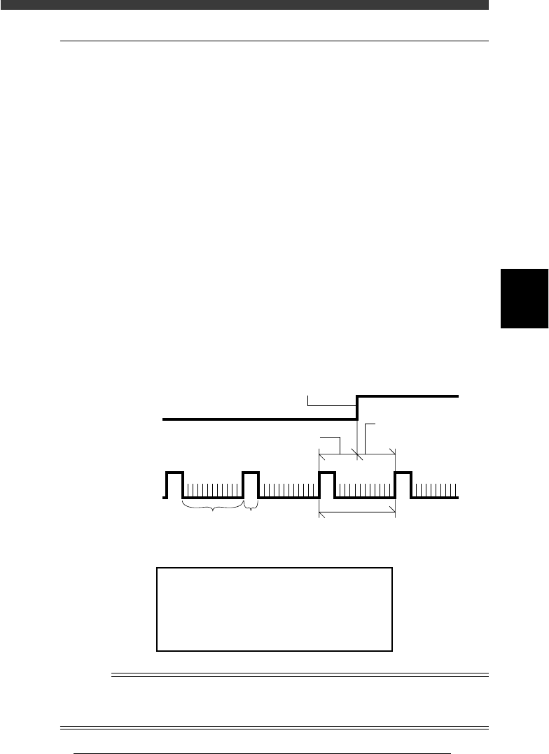
Machine reference
The built-in motor encoder of each axis issues a “0” pulse each time one
rotation is complete. When return-to-origin is performed, there will be a
difference in distance between the position where the origin signal is
detected and the point at which the next encoder “0” pulse is received
(origin position is actually set). This is called the machine reference and is
usually expressed as a percentage, with 100% being equal to one full
rotation of the motor. The machine reference value must be in the range
from 35% to 65%.
Machine reference
43402-D8-00
Encoder signal
Origin sensor
signal
Machine reference (Z axis)
Origin signal
One rotation of motor
A, B phase 0 phase
Machine reference
(W, X, Y, T, R axes
)
Machine reference display
47409-D8-00
Machine Reference
Hit Any Key.
X1 = 55 %
W2 = 52 %
X2 = 48 %
W1 = 50 %
Y1 = 55 %
W2 = 52 %
Y2 = 48 %
W4 = 50 %
Z1 = 55 %
T1 =52 %
Z2 = 48 %
R1 = 55 %
R2=52 %
n
NOTE
The machine reference of each axis is preadjusted at the factory prior to shipping. It is
unlikely that you will need to readjust these values under normal operating conditions. If
readjustment is required, please contact your YAMAHA sales office or dealer.
4
-10
Service Manual
Chapter 4
SED8013110
4
Machine adjust mode
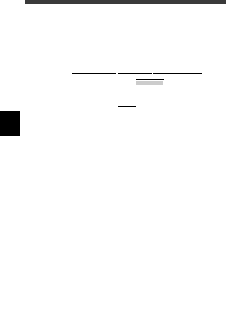
3. Adjust target
<3/3/B1>
When you select <3/3/ MCH_ ADJUST> − <B1 ADJUST TARGET>, the
adjustment menu window appears as shown below. Each adjustment item
and is described in the following sections.
Adjustment menu window in Machine Adjust mode
47410-D8-00
<<<APPLICATION>>> 3/MAINTE/M
<<MODE>> 3/MCH_ADJUST
<COMMAND_LIST> B/SAVE & QUIT
B1 ADJUST TARGET
Object
Soft. Limit
Position
Vacuum Level
Moving Camera
Multi Camera
R Axis Accuracy
Mount Feedback