YV180X_Mainte_E.pdf - 第43页
3 -6 Service Manual Chapter 3 3 Machine data edit mode SED8013110 2.2 Of fset Selecting “ Offset ” from the “ Head ” submenu opens the Head Of fset screen showing the positional of fset of each head relativ e to Head 1. …
3
-5
Service Manual
3
Machine data edit mode
Chapter 3
SED8013110
2.1 Vacuum level
Selecting “Vacuum Level” from the “Head” submenu opens another
submenu box to show the reference vacuum levels of each head using
different nozzles or same nozzle. Either submenu shows the reference
vacuum levels the machine uses to determine whether a component is
picked up or mounted.
A nozzle picks up a component by a vacuum pressure (negative pressure).
This negative pressure is then inverted to a positive pressure at the instant
the nozzle mounts the component on a PCB. This pressure is constantly
monitored on a scale of 0 to 255 levels (the larger the value, the higher the
vacuum intensity). On this monitoring scale, a low level and high level are
specified as the reference pickup and mount vacuum levels respectively.
Vacuum Level screen (using different nozzles)
47321-D8-00
Low level
111
102
108
103
104
94
106
105
High level
213
209
210
207
208
205
208
207
<<<APPLICATION>>> 3/MAINTE/M
<<MODE>> 2/MCH_DATA
OBJECT
Vacuum Level
Head No.
Head 1 A
Head 2 A
Head 3 A
Head 4 A
Head 5 A
Head 6 A
Head 7 A
Head 8 A
Low level
178
175
180
171
180
167
175
180
High level
208
210
212
205
210
205
213
206
TYPE- 71 TYPE- 72 TYPE- 73
Each Nozzle Ver.
Low level
59
80
59
82
58
70
55
80
High level
214
202
214
201
210
197
214
202
Vacuum Level screen (using same nozzle)
47303-D8-00
<<<APPLICATION>>> 3/MAINTE/M
<<MODE>> 2/MCH_DATA
Head No.
Head 1 A
Head 2 A
Head 3 A
Head 4 A
Head 5 A
Head 6 A
Head 7 A
Head 8 A
Low level
100
100
100
100
100
100
100
100
OBJECT
Vacuum Level
TCH.UNIT SPEED
- - - - - - - -
High level
180
180
180
180
180
180
180
180
Low level Reference pickup vacuum pressure used to check
that a component is being picked up by the nozzle.
High level Reference mount vacuum pressure used to check
that a component has been mounted on a PCB
(separated from the nozzle).
n
NOTE
Reference vacuum pressures can be automatically optimized with the Vacuum Level
command in the Machine Adjust mode.

3
-6
Service Manual
Chapter 3
3
Machine data edit mode
SED8013110
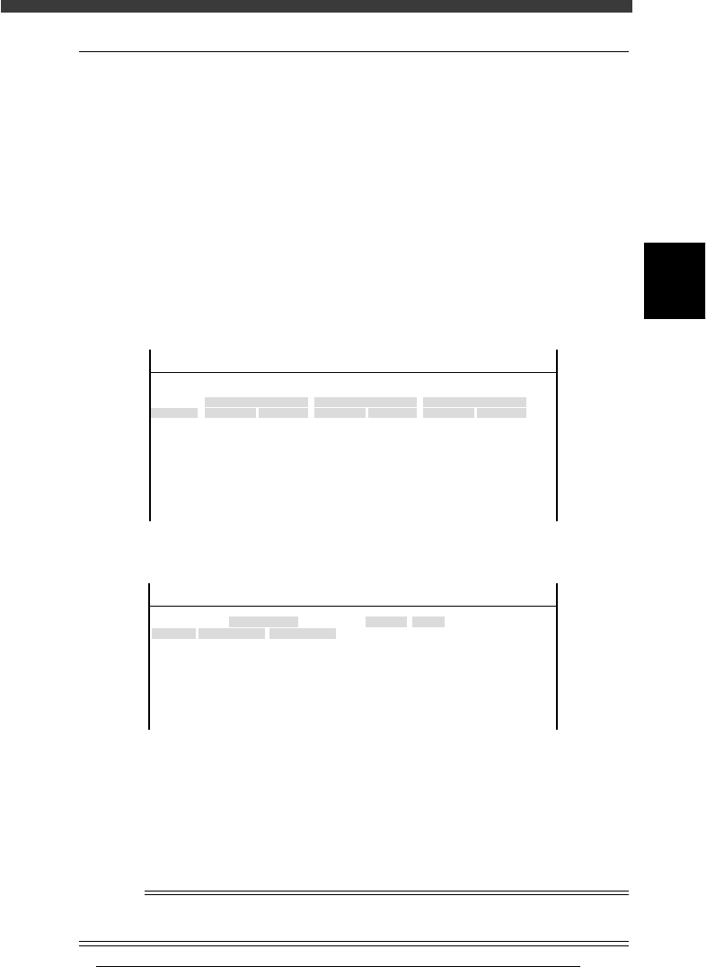
2.2 Offset
Selecting “Offset” from the “Head” submenu opens the Head Offset screen
showing the positional offset of each head relative to Head 1.
Head Offset screen
47304-D8-00
Head No.
Head 1 A
Head 2 A
Head 3 A
Head 4 A
Head 5 A
Head 6 A
Head 7 A
Head 8 A
HeadType
Manual NzlChg
AutoNzlChg
Manual NzlChg
AutoNzlChg
Manual NzlChg
AutoNzlChg
Manual NzlChg
AutoNzlChg
X
0.000
15.992
32.020
48.004
64.008
79.996
96.033
112.030
Y
0.000
0.008
0.026
-0.028
0.018
0.003
0.003
-0.002
Z
0.000
-0.010
0.010
-0.020
-0.010
-0.030
0.010
-0.050
Nozzle
TYPE-72
TYPE-72
TYPE-72
TYPE-72
TYPE-72
TYPE-72
TYPE-72
TYPE-72
OBJECT
Head Offset
TCH. UNIT SPEED
- - - - - - - -
<<<APPLICATION>>> 3/MAINTE/M
<<MODE>> 2/MCH_DATA
HeadType Set to “AntoNzlChg” for FNC heads (Heads 2, 4, 6,
8) and to “ManualNzlChg” for the other heads
(Heads 1, 3, 5, 7).
X, Y, Z Shows the positional offset (mm) of each head
relative to Head 1. Head 1 is always “0.000”.
Nozzle Specifies the nozzle type attached to each head.
This parameter is enabled only when “HeadType” is
set to “Fixed Nozzle” or “DispenseNzl”.
n
NOTE
Head offset XYZ can be automatically adjusted by running the AMF (auto mount
feedback) utility. See the AMF manual for details.

3
-7
Service Manual
3
Machine data edit mode
Chapter 3
SED8013110
2.3 Down offset
Selecting “Down Offset” from the “Head” submenu opens the Head Down
Offset screen as shown below. Data entered here are offset settings for
correcting a positional shift of the rotational center of each head which
occurs when it descends to pick up a component, lighting method, etc.
Head Down Offset screen
47305-D8-00
<<<APPLICATION>>> 3/MAINTE/M
<<MODE>> 2/MCH_DATA
Head No.
Head 1 A
Head 2 A
Head 3 A
Head 4 A
Head 5 A
Head 6 A
Head 7 A
Head 8 A
OBJECT
Vacuum Level
TCH.UNIT SPEED
- - - - - - - -
Y
0.000
0.000
0.000
0.000
0.000
0.000
0.000
0.000
X
0.000
0.000
0.000
0.000
0.000
0.000
0.000
0.000
X correct
0.000
0.000
0.000
0.000
0.000
0.000
0.000
0.000
Y correct
0.000
0.000
0.000
0.000
0.000
0.000
0.000
0.000
HeadType
Fore
Fore
Fore
Fore
Fore
Fore
Fore
Fore
FIneMode
impossible
impossible
impossible
impossible
impossible
impossible
impossible
impossible
X, Y Shows XY offset (mm) of the rotational center of
each head when it descends to pick up a compo-
nent. This parameter affects the component pickup
action only, and does not affect the mounting
accuracy.
X, Y correct Shows XY offset to correct a mounting position shift
caused by a component which is not perpendicular
to the PCB surface when picked up by a nozzle. Set
this parameter to “0.000” in most cases.
HeadType Shows the lighting method that matches each head.
All heads of the YV180X should be set to “Fore”.
FineMode This function cannot be used with the YV180X and
should be set to “impossible”.
n
NOTE
Head down offset can be automatically adjusted by running the AMF (auto mount
feedback) utility. See the separate AMF manual for details.