YV180X_Mainte_E.pdf - 第132页
5 -3 SED8013110 Service Manual Chapter 5 5 Manual mode 1. Manual mode main menu Manual (3/4/MANUAL) mode allows you to check the mechanical or electrical on/off operation during adjustment. Y ou can also manipulate the Y…

Chapter 5
Manual mode
1. Manual mode main menu 5-3
2. I/O utility <3/4/A> 5-4
2.1 Input/output monitor <3/4/A1> ..................................................................5-4
2.2 Feeder out monitor <3/4/A2> .....................................................................5-6
2.3 Vacuum IN monitor <3/4/A4>....................................................................5-6
2.4 Change nozzle <3/4/A5> ...........................................................................5-7
2.5 Conveyor units <3/4/A0> ...........................................................................5-7
3. Servo control <3/4/B> 5-8
3.1 Select servo motor <3/4/B1> ......................................................................5-8
3.2 Running speed <3/4/B2>............................................................................5-8
3.3 Point move <3/4/B3> .................................................................................5-9
3.4 Initialize servo origin <3/4/B6> ..................................................................5-9
3.5 Exit from manual <3/4/B0> ......................................................................5-10
MANUAL mode allows running various commands which are useful
during adjustment of the machine. This chapter explains what these
commands do and how to read the input/output monitor.
5
-3
SED8013110
Service Manual
Chapter 5
5
Manual mode
1. Manual mode main menu
Manual (3/4/MANUAL) mode allows you to check the mechanical or
electrical on/off operation during adjustment. You can also manipulate the
YPU joystick to move a servo-controlled unit manually along its axis.
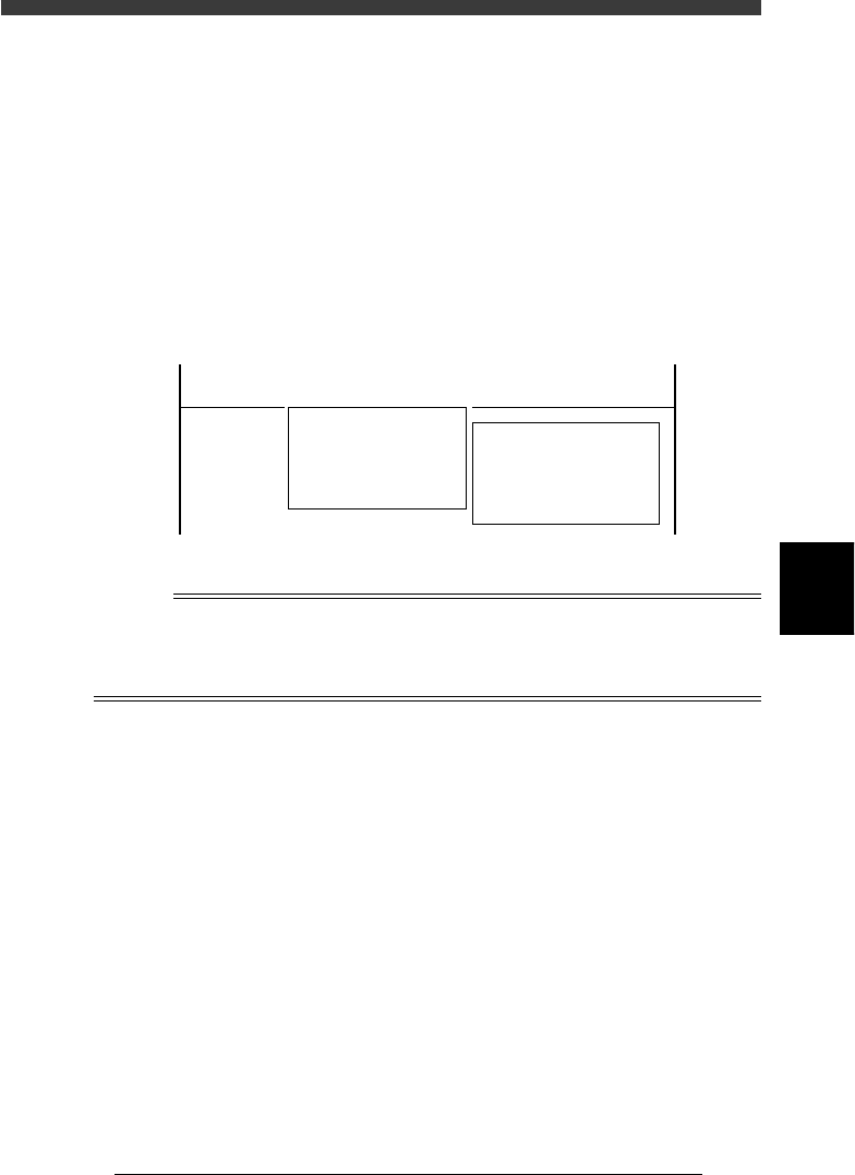
When you enter <3/4/ MANUAL> mode, the two command menu
windows <A/IO_UTILITY> and <B/SERVO_CONTROL> can be
selected. This section explains these command menus. You can also refer to
the help message as necessary for information about each command, which
appears on the operation monitor by pressing the [F1] key.
Command menu windows selectable from MANUAL mode
47501-D8-00
<<<APPLICATION>>> 3/MAINTE/M
<<MODE>> 4/MANUAL
<COMMAND_LIST> A/IO_UTILITY B/SERVO_CONTROL
A1 INPUT/OUTPUT MONITOR
A2 FEEDER OUT MONITOR
A3
A4 VACUUM IN MONITOR
A5 CHANGE NOZZLE
A6 ATS/YTF/ PALETTE
A0 CONVEYOR UNITS
B1 SELECT SERVO MOTOR [AXIS]
B2 RUNNING SPEED [SPEED]
B3 POINT MOVE
B4
B5
B6 INIT. SERVO ORIGIN
B0 EXIT FROM MANUAL
Reference
This MANUAL mode of MAINTENANCE Manager is exactly the same as MANUAL mode
of the OPERATION and DATA Managers.
Since an optional tray changer (YTF80W, ATS20) cannot be connected to the YV180X, the
<A6 ATS/YTF PALLET> command is invalid.
5
-4
Service Manual
Chapter 5
SED8013110
5
Manual mode
2. I/O utility
<3/4/A>
The <3/4/A IO UTILITY> menu has commands frequently used when
checking the input/output digital signal status of the machine. To run a
command, move the cursor to the command and press the [ENTER] key or
directly enter the corresponding number. The function of each command is
explained below.
2.1 Input/output monitor
<3/4/A1>
Use this command to check the input/output digital signal status of the
machine. When you run <3/4/A1 INPUT/OUTPUT MONITOR>, the
DISP. TYPE submenu box appears for selecting the display method as
shown below.
INPUT/OUTPUT MONITOR command and submenu
47502-D8-00
DISP. TYPE
ALL
SELECTION
<<<APPLICATION>>> 3/MAINTE/M
<<MODE>> 4/MANUAL
<COMMAND_LIST> A/IO_UTILITY B/SERVO_CONTROL
A1 INPUT/OUTPUT MONITOR
A2 FEEDER OUT MONITOR
A3
A4 VACUUM IN MONITOR
A5 CHANGE NOZZLE
A6 ATS/YTF/ PALETTE
A0 CONVEYOR UNITS
You can choose the desired method.
1) Choosing “ALL” allows you to view the entire digital I/O status.
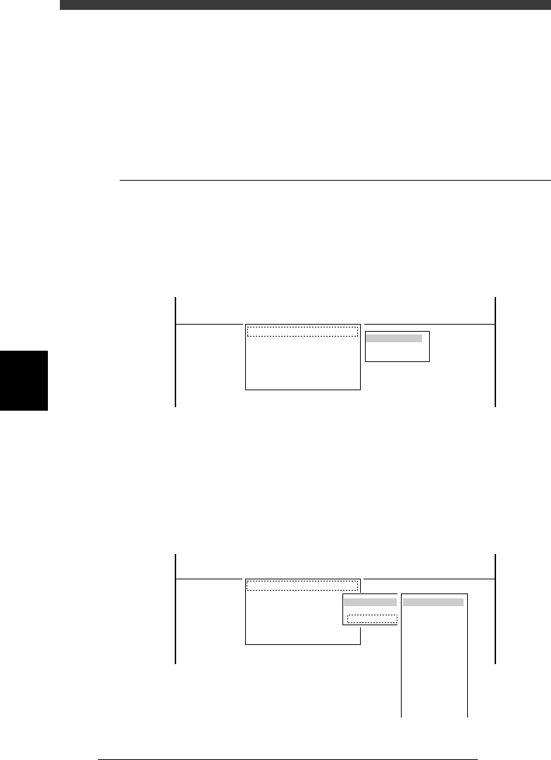
2) Choosing “SELECTION” further displays the submenu from which you
can choose the specific group (such as “CONVEYOR” and “HEAD”).
Submenu display when “SELECTION” is chosen
47503-D8-00
OBJECT
CONVEYOR
HEAD
LIGHTING
FEEDER
NZL . STN.
DMP. STN.
TRAY CHANGER
INTER LOCK
ORG. /LIMIT
OPTION
IO SEQUENSE
WAFER
OTHERS
DISP. TYPE
ALL
SELECTION
<<<APPLICATION>>> 3/MAINTE/M
<<MODE>> 4/MANUAL
<COMMAND_LIST> A/IO_UTILITY B/SERVO_CONTROL
A1 INPUT/OUTPUT MONITOR
A2 FEEDER OUT MONITOR
A3
A4 VACUUM IN MONITOR
A5 CHANGE NOZZLE
A6 ATS/YTF/ PALETTE
A0 CONVEYOR UNITS