YV180X_Mainte_E.pdf - 第107页
4 -49 SED8013110 Service Manual Chapter 4 4 Machine adjust mode u Follow the message on the operation monitor to quit the calibration. Release the conveyor units, press the emergency stop button and remove the PCB. i Sav…
4
-48
Service Manual
Chapter 4
SED8013110
4
Machine adjust mode
e Check safety, then press the [ENTER] key again.
The head assembly moves to above the PCB origin and the teaching
screen appears as shown below.
47442-C0-00
A428
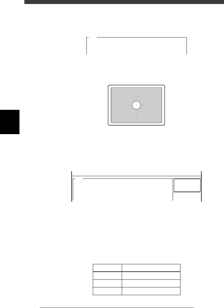
<<Teaching>>
Please position the cross hair cursor over the
fiducial mark on screen......
r Position the fiducial mark in the center of the screen.
Manipulate the YPU joystick to align the mark with the cross cursor on the
screen.
43417-C0-00
t Press the [ENTER] key to start calibration.
The moving camera moves in both X and Y directions. The camera scale is
calibrated based on the amount of movement on the vision monitor and
the results are then displayed on the screen.
47443-D8-00
<<<RESULT>>>
The results of the moving camera scale adjustment are
as follows.
To save the results in memory, press the [ENTER] key
(the results are . . .
Scale_x
Scale_y
Angle
=
=
=
10.30
10.30
0.05
<<MODE>> 3/MCH_ADJUST
A431
y Check that the results are within the specified range.
When the moving camera height and angle are correctly adjusted, the
camera scale and angle should be within the specified range. If not, you
will need to readjust “FOV & focus” and then recalibrate the camera scale
to check the results. again.
Specified range of moving camera scale and angle
45405-D8-00
Parameter
Scale x
Scale y
Angle r
Specified Range
10.2±0.2µm (10.0 to 10.4µm)
10.2±0.2µm (10.0 to 10.4µm)
0±0.5°

4
-49
SED8013110
Service Manual
Chapter 4
4
Machine adjust mode
u Follow the message on the operation monitor to quit the
calibration.
Release the conveyor units, press the emergency stop button and remove
the PCB.
i Save the calibration settings.
Select <B2 SAVE DATA> or <B0 SAVE & QUIT> and press the [ENTER]
key. (To quit without saving, select <B3 RECOVER ADJUST> or <B7
QUIT> and press the [ENTER] key.)
4
-50
Service Manual
Chapter 4
SED8013110
4
Machine adjust mode
3.5 Multi-vision camera
The YV180X uses a CCD linear image sensor called the multi-vision
camera for component recognition. The following parameters of the multi-
vision camera must be adjusted correctly for accurate recognition of
components. To make these adjustments easier, use the adjustment utilities
in the MAINTENANCE Manager and the Adjust Assistant commands in
the DATA Manager.
Adjustment parameters of the multi-vision camera
44406-D8-00
Fov & Focus
Brightness level
Camera scale
Dual recognition
Marker
The focus adjuster tool (KV1-M8803-00X) is required.
The light adjuster tools (KM1-M8806-0XX, KV7-M8806-0XX)
are required.
An SOP or QFP component is used. *
An SOP or QFP component is used. *
The marker provided on the head assembly is used.
Adjustment item Remarks
* For more accurate adjustments, we recommend using a glass QFP (sold separately)
specially designed for making adjustments.
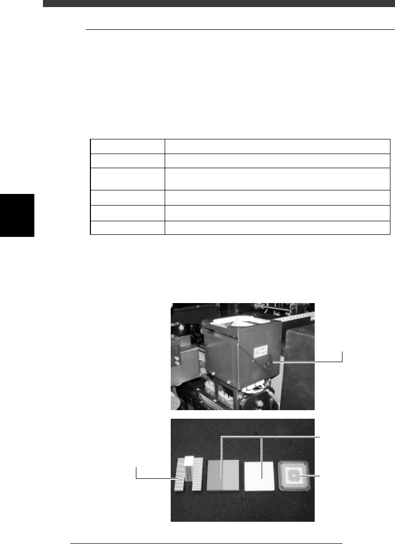
Multi-vision camera and adjustment tools (option)
43422-D8-00
Multi-view camer
a
Glass QFP
Light adjuster
Focus adjuster