YV180X_Mainte_E.pdf - 第153页
6 -15 SED8013110 Service Manual Chapter 6 6 Conveyor unit and air supply unit adjustment 47605-D8-00 CONV CONV CONV CONV CONV CONV CONV CONV OUT 0 0 0 0 0 0 00000000 00000000 0 0 0 0 0 0 0 0 IN T1920 T1922 T1923 T1924 T1…
6
-14
Service Manual
Chapter 6
SED8013110
6
Conveyor unit and air supply unit adjustment
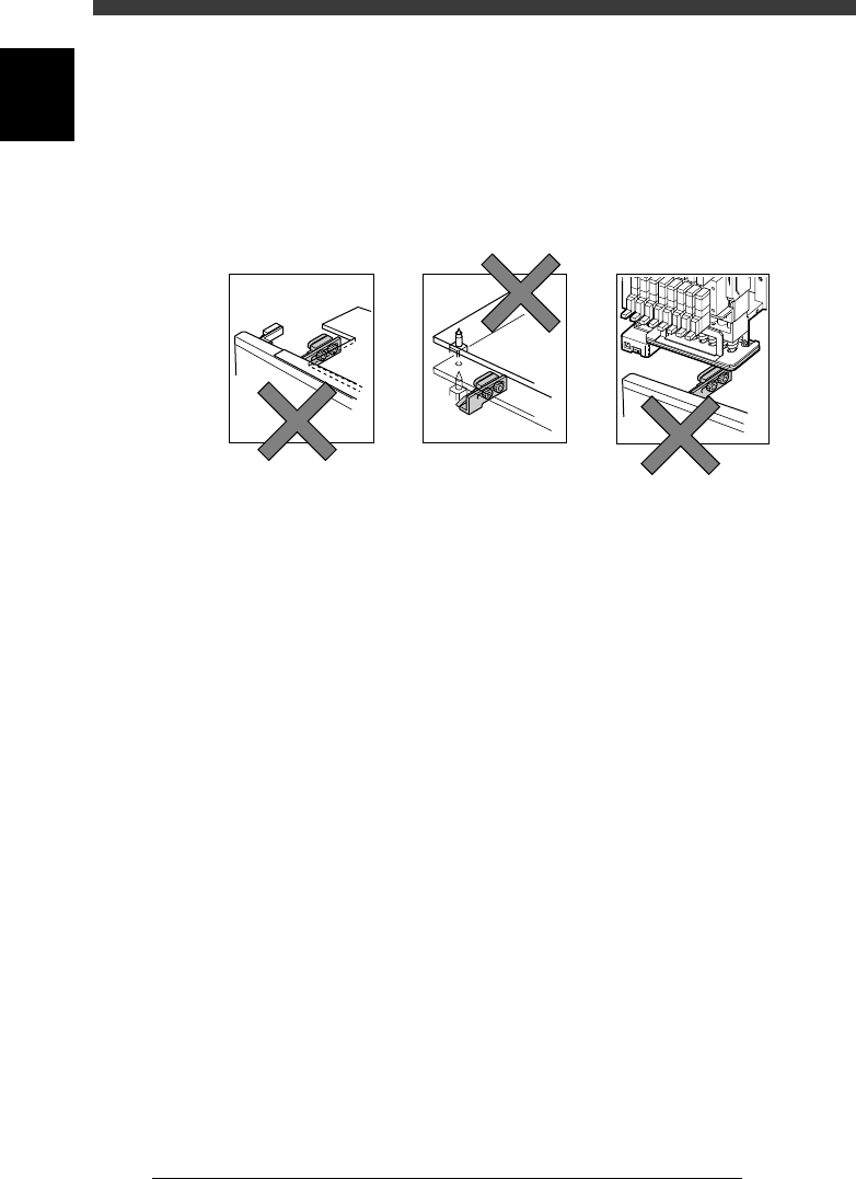
Checking PCB detection sensor operation
The sensors may fail to detect a PCB due to factors such as the orientation,
distance and angle at which it is attached. The sensors may also be affected
by strong extraneous light, excessive dust, and the shape (hole or notch)
and color of the PCB. Using PCBs on which you actually mount
components, check that the sensors can detect them reliably.
PCB sensor detection errors
43603-D8-00
Irregular shape PCB Misdetection due to
change in distance to PCB
Detected part of head assembly
(incorrect position setting)
To check the PCB sensor functions, refer to the procedure outlined below.
1 Prepare the PCBs.
Prepare several PCBs that you actually use for component mounting.
2 Adjust the conveyor width according to the size of the
PCBs.
To adjust the conveyor width, you can use the <3/4/A0 CONVEYOR
UNITS> − ”CONV. WIDTH” command.
e
3 Press the emergency stop button, then place the PCBs on
the conveyor.
Place a PCB over each sensor along the conveyor. To clamp the PCB in the
mounting position over the sensor N1033, the <2/1/B7 CONVEYOR
UNITS> command will prove convenient.
4 Open the input monitor and check the detection status.
1. Select <3/4/A1 INPUT/OUTPUT MONITOR> and press the [ENTER]
key.
2. Use the [TAB] and arrow keys to line up the cursor with “N1030” to
“N1036”.
The input monitor digit reads “1” when a PCB is detected, and reads
“0” when not detected. Check that the digit of each sensor reads “1”.
Also check that the detection status of “N1054” and “N1154” (PCB
sensors in the mounting position) does not vary even if the locate pins
and push-up plate are raised to clamp the PCB.

6
-15
SED8013110
Service Manual
Chapter 6
6
Conveyor unit and air supply unit adjustment
47605-D8-00
CONV
CONV
CONV
CONV
CONV
CONV
CONV
CONV
OUT
0
0
0
0
0
0
00000000
00000000
0
0
0
0
0
0
0
0
IN
T1920
T1922
T1923
T1924
T1867
T1921
T4E60
T4E70
N1030
N1121
N1123
N1033
N1034
N1031
N1035
N1032
I/O MONITOR DISP. TYPE SELECTION
MAIN STOPPER ( A TABLE ) UP
OFF 0 / ON 1
ENT. CONVEYOR ENTRANCE
NOT DETECT 0 / DETECT 1
CONV
CONV
CONV
CONV
CONV
CONV
CONV
CONV
OBJECT CONV
<<<APPLICATION>>> 3/MAINTE/M
<<MODE>> 4/MANUAL
↑
↓
↑
↓
5 If necessary, adjust the position of the PCB detection
sensor.
Loosen the screws securing the sensor, and adjust the position, orientation
or angle at which it is attached.
n
Note
When adjusting the position of PCB detection sensors, check that they are not above the
separation points of a multi-block PCB.
6 Remove the PCBs from the conveyor.
6
-16
Service Manual
Chapter 6
SED8013110
6
Conveyor unit and air supply unit adjustment
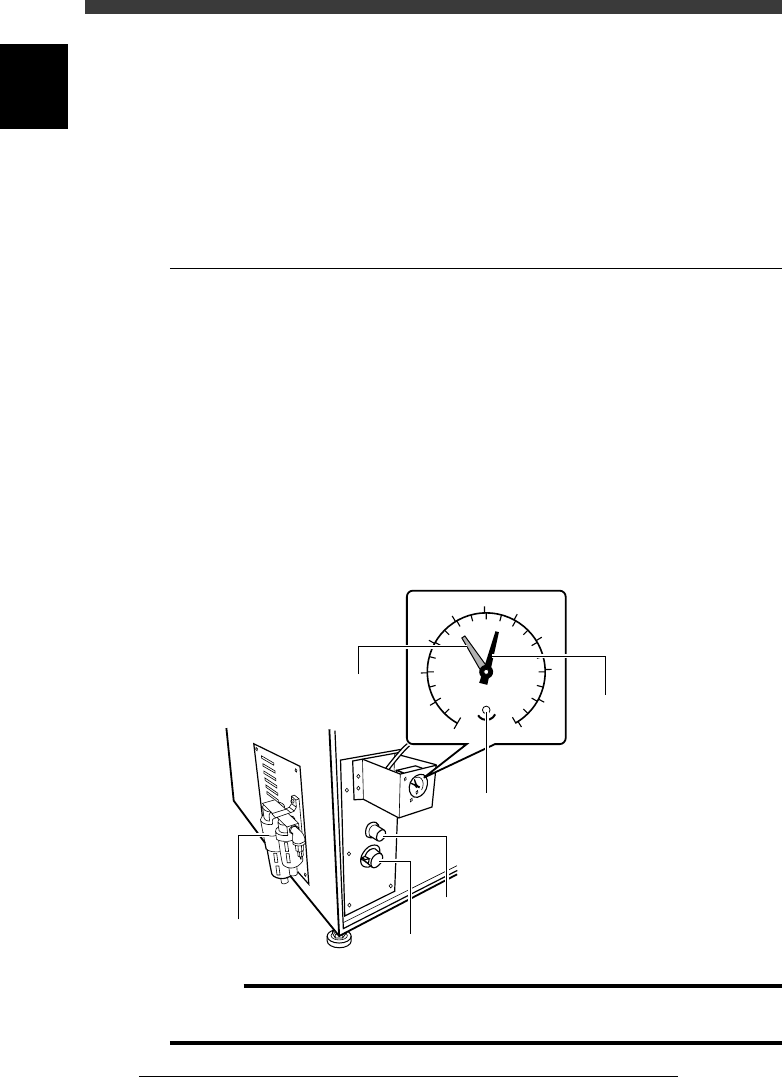
2. Air supply unit
The air supply unit is located inside the left side of the machine, along with
a pressure regulator. The air pressure indicator is located on the front lower
left of the machine. The pressure regulator must be set correctly in order to
provide optimum air pressure for the vacuum ejector and pneumatic
devices.
2.1 Air pressure regulator
The air pressure regulator can be adjusted with the valve control knob as
follows. Before making this setting, be sure that the pressure from the
primary air supply is between 0.6 and 0.7MPa.
1 Open the lower right panel on the front side of the
machine.
The pressure control valve knob and residual pressure bleed off knob are
located inside the panel.
2 Adjust the air pressure.
Turn the pressure control valve knob so that the air pressure (black needle)
is set at 0.55MPa.
Pressure regulator and valve control knob
43607-C0-00
0
1
2
3
4
5
6
7
8
9
10
0.0
0.1
0.2
0.3
0.4
0.5
0.6
0.7
0.8
0.9
1.0
MPa
(kgf/cm )
2
Pressure indicator
Pressure bleed off knob
Adjustment screw
(for setting pressure drop detection level)
Pressure indicator needle (black
)
Pressure drop detection level (red)
Pressure control valve knob
Pressure regulator
c
Caution
If this pressure setting is incorrect, the vacuum ejector cannot work adequately and air
cylinders become unstable. Be sure that the pressure is set at the specified value.