YV180X_Mainte_E.pdf - 第69页
4 -11 SED8013110 Service Manual Chapter 4 4 Machine adjust mode 3.1 Software limits When you select <3/3/B1 ADJUST T ARGET> - “ Soft Limit ” , the Software Limit screen opens as shown belo w . Y ou can check and ad…
4
-10
Service Manual
Chapter 4
SED8013110
4
Machine adjust mode
3. Adjust target
<3/3/B1>
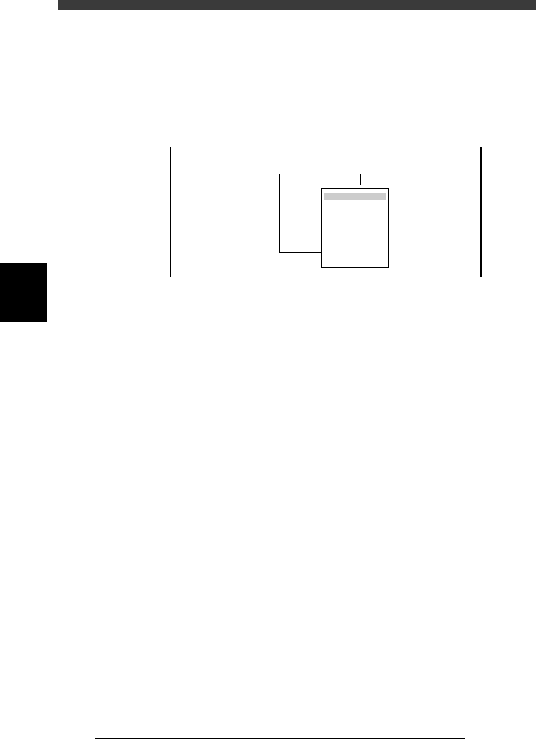
When you select <3/3/ MCH_ ADJUST> − <B1 ADJUST TARGET>, the
adjustment menu window appears as shown below. Each adjustment item
and is described in the following sections.
Adjustment menu window in Machine Adjust mode
47410-D8-00
<<<APPLICATION>>> 3/MAINTE/M
<<MODE>> 3/MCH_ADJUST
<COMMAND_LIST> B/SAVE & QUIT
B1 ADJUST TARGET
Object
Soft. Limit
Position
Vacuum Level
Moving Camera
Multi Camera
R Axis Accuracy
Mount Feedback
4
-11
SED8013110
Service Manual
Chapter 4
4
Machine adjust mode
3.1 Software limits
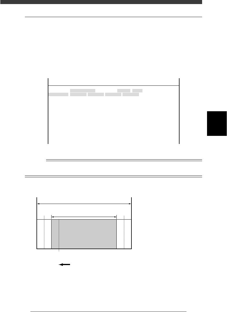
When you select <3/3/B1 ADJUST TARGET> - “Soft Limit”, the Software
Limit screen opens as shown below. You can check and adjust here the
software limit parameters to determine the axis movement range and initial
position parameters used as a reference point for axis movement.
These parameters must be set correctly to maintain accurate machine
movement and component mounting.
Software Limit screen
47458-D8-00
<<<APPLICATION>>> 3/MAINTE/M
<<MODE>> 2/MCH_DATA
OBJECT
Software Limit
TCH.UNIT SPEED
- - - - - - - -
-direct.
-277.973
-272.227
-274.202
-283.200
-0.238
-0.154
-32.840
-91.717
-88.200
-26.815
-36.140
-360.000
-360.000
Init. Pos
-323.600
-321.790
-323.650
-328.650
0.000
0.000
360.271
-25.815
448.199
15.100
11.000
Init. Mov
395.000
+direct.
11.323
13.753
11.993
7.113
23.477
23.076
842.547
942.344
943.970
452.790
449.199
360.000
360.000
Axis
W1/RIGHT
W2/A-TBL
W3/B-TBL
W4/LEFT
Z1/A-TBL
Z2/B-TBL
T1/MAIN
X1/A-TBL
X2/B-TBL
Y1/A-TBL
Y2/B-TBL
R1/A-TBL
R2/B-TBL
Reference
The Software Limit screen opens by selecting “Position” - “Soft Limit” in MCH_DATA
mode.
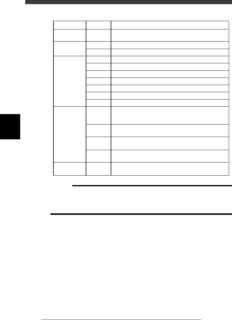
Software limits and axis movement range
43403-C0-00
A
A :
B :
C :
D :
E :
F :
Movable range
Movement range allowed
by software limits
Software limits
Secondary limits (X, Y)
Origin position
Mechanical limits
B
Return to ori
g
in direction
Mechanical stopper
Mechanical stopper
FDCE CDF
▲▲▲▲ ▲▲▲
4
-12
Service Manual
Chapter 4
SED8013110
4
Machine adjust mode
Parameter items relating to servo-controlled axes
45401-D8-00
Machine
reference
Secondary
limit
Software limit
Initial position
Initial
movement
W, Z, X,
Y, R, T
X
Y
W
Z
X (A table)
X (B table)
Y
R
T
W
Y
R
T
T
35 to 65% (See "2.7"in Chapter 4.)
1.0mm inwards from the mechanical limit
3.0mm inwards from the mechanical limit
3.0mm inwards from the mechanical limit
1.0mm inwards from the mechanical limit
1.0mm inwards from the secondary limit
1.0mm inwards from the secondary limit
3.0mm inwards from the mechanical limit
Fixed to 360˚ on the plus side and -360˚ on the minus side
5.0mm inwards from the mechanical limit
Value obtained by subtracting 0.5mm from the conveyor
width when the axis is at the origin, then expressed with
minus sign
Position at which all the A/B tables, carry-in conveyor and
carry-out conveyor are aligned straight during PCB transfer
Angle at which the nozzle holder leaf springs are parallel to
the X-axis arm.
Position at which the A-table main stopper is in contact
with the center transfer hook
This is the T-axis stroke for transferring PCBs.
Fixed to 395mm (standard machine).
SettingAxisItem
c
CAUTION
The software limits, initial positions and initial movement settings are preset at the
factory prior to shipping. It is unlikely that you will need to readjust them. If readjust-
ment is required, make correct settings while referring to the above points. For more
details, please contact YAMAHA sales office or dealer.