YV180X_Mainte_E.pdf - 第119页
4 -61 SED8013110 Service Manual Chapter 4 4 Machine adjust mode q Check safety , then press the [ENTER] key again. The head assembly moves and passes repeatedly over the multi-vision camera and the camera scale is calibr…
4
-60
Service Manual
Chapter 4
SED8013110
4
Machine adjust mode
7 Enter the component database No. and press the [ENTER]
key.
Enter here the database No. of the component you have prepared.
47449-C0-00
Enter the component database number ...
The specified component uses ...
CAUTION! The axes will move.
Please pick up the specified component with the
specified head, or ...
Database No. 2
A466
A303
A373
A461
Step7
Step8,
9
8 Check safety, then press the [ENTER] key twice.
The head assembly moves to the component pickup point.
Reference
When you are using a tape feeder, the feeder set No. input box appears, so follow the
message on the screen. In this case, the component is automatically picked up and Steps 9
to 10 are skipped.
e
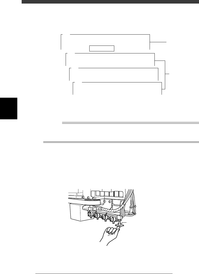
9 Press the emergency stop button, then attach the compo-
nent to Head 1 by hand.
This step is not necessary when the component was left attached to Head
1 after executing the Adjust Assistant in the previous procedure.
Attaching the component to Head 1
43414-D8-00
Attach component to Head 1.
0 Cancel emergency stop.
Release the emergency stop button by turning it clockwise and press the
[READY] button.
4
-61
SED8013110
Service Manual
Chapter 4
4
Machine adjust mode
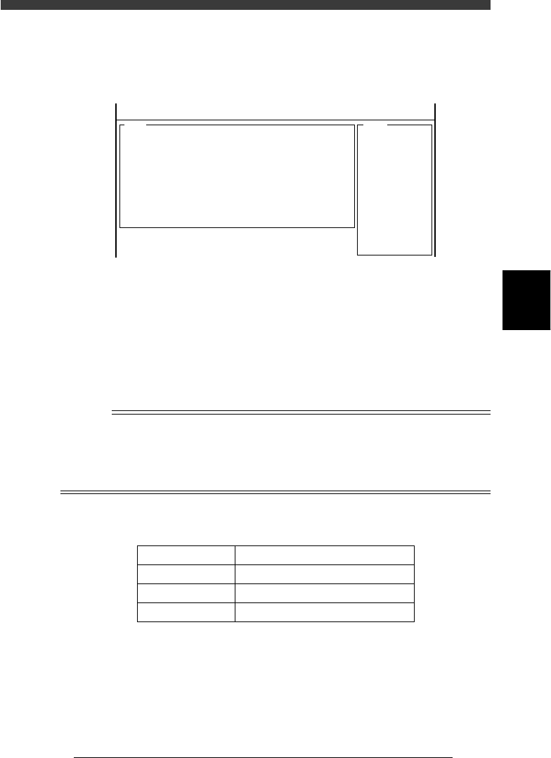
q Check safety, then press the [ENTER] key again.
The head assembly moves and passes repeatedly over the multi-vision
camera and the camera scale is calibrated. The results are then displayed
on the upper right of the operation monitor.
47450-D8-00
<<MODE>> 3/MCH_ADJUST
<COMMAND_LIST> B/SAVE & QUIT
<<<Result>>>
The results of calculating the scales of the
multi-vision camera are as follows. . . .
A542
0.00
48.83
55.83
382.93
( 0.002)
-0.03
( -0.119)
-0.55
( -0.164)
0.000
-0.106
3.301
1.256
0.7847
= 5
=
=
=
=
=
=
=
=
=
=
=
Camera
Distance
Scale_x
Scale_y
Cam.posx
Cam.posy
Cam.posr
Div_x
Div_y
Cam.corx
Cam.cory
Rat
Atable
w Press the [ENTER] key to save the calibrated results.
If you want to cancel the results, press the [ESC] key.
e When the calibration is complete, dump the component.
Follow the message on the operation monitor.
r Save the calibrated data.
Select <B2 SAVE DATA> or <B0 SAVE & QUIT> and press the [ENTER]
key. (To quit without saving, select <B3 RECOVER ADJUST> or <B7
QUIT> and press the [ENTER] key.
n
NOTE
When the camera scale is successfully calibrated, the scale values should be within the
typical range shown in the table below. If not, readjust “FOV & Focus” and “Brightness
Level”, and then make the camera scale calibration again to check the results.
The camera scale calibrated here is stored in the “Camera” - “Vision Parameter”
information in MCH_DATA mode (see “3.2” in Chapter 3.).
Typical range of multi-camera scale
45409-D8-00
Parameter
Scale X,Y
Camera pos X,Y
Camera pos r
Typical Range
48.78±0.98 (47.80 to 49.76) µm/pixel
47.00±15µm
0º±1º
t Return the edited data in the database to the original
setting.
Return the edited data to the original setting as necessary. If you want to
keep this edited data, entering a proper comment is advisable.
4
-62
Service Manual
Chapter 4
SED8013110
4
Machine adjust mode
3.5.4 Adjusting the dual-direction recognition
offset
The multi-vision camera can recognize components traveling from right
and from left. This recognition offset between the dual directions is entered
as the “Dual Rec. Offset” data on the Position screen, and must be adjusted
correctly for accurate mounting. It is recommended that you use an SOP or
QFP such as those used in the camera scale adjustment.
Reference
YAMAHA uses a glass QFP with minimal warp and distortion, specially designed for
adjustment work. To make more accurate adjustments, we recommend using this glass
QFP (sold separately).
e
1 Check that an appropriate nozzle is attached to Head 1.
Press the emergency stop button, then attach a Type 73A or 74A nozzle to
Head 1. (If using a glass QFP, attach a Type 74A nozzle.)
2 Cancel emergency stop.
When the machine is in emergency stop, release the emergency stop
button by turning it clockwise and press the [READY] button.
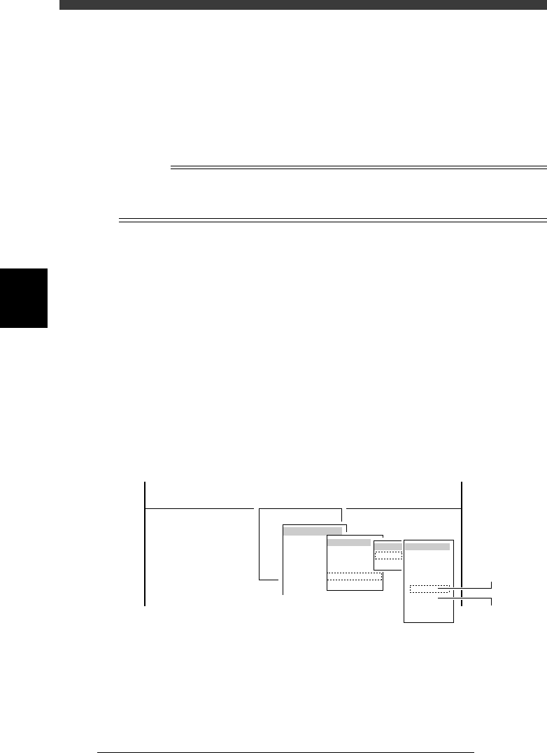
3 Run the “Multi Camera” − “Dual Recognition” command.
1. Select <3/3/B1 ADJUST TARGET> − ”Multi Camera” - “Dual Recogni-
tion” and press the [ENTER] key.
2. Select the conveyor table and the camera No. by pressing the [ENTER]
key.
The A-table multi-vision camera is designated “Cam. 5” and the B-table
multi-vision camera “Cam. 6”.
47445-D8-C0
B1 ADJUST TARGET
Object
Multi Camera
<<<APPLICATION>>> 3/MAINTE/M
<<MODE>> 3/MCH_ADJUST
<COMMAND_LIST> B/SAVE & QUIT
Target
FOV & Focus
Brightness
Camera Scale
Dual Recognition
Marker
table
A table
B table
Target
Cam. 1
Cam. 2
Cam. 3
Cam. 4
Cam. 5
Cam. 6
Cam. 7
Cam. 8
A Table
Multi Camer
a
B Table
Multi Camer
a