YV180X_Mainte_E.pdf - 第56页
3 -19 Service Manual Chapter 3 SED8013110 3 Machine data edit mode 4.3 Position Selecting “ Position ” from the “ Machine ” submenu opens the Position screen showing the position of eac h hardware de vice versus the orig…
3
-18
Service Manual
Chapter 3
3
Machine data edit mode
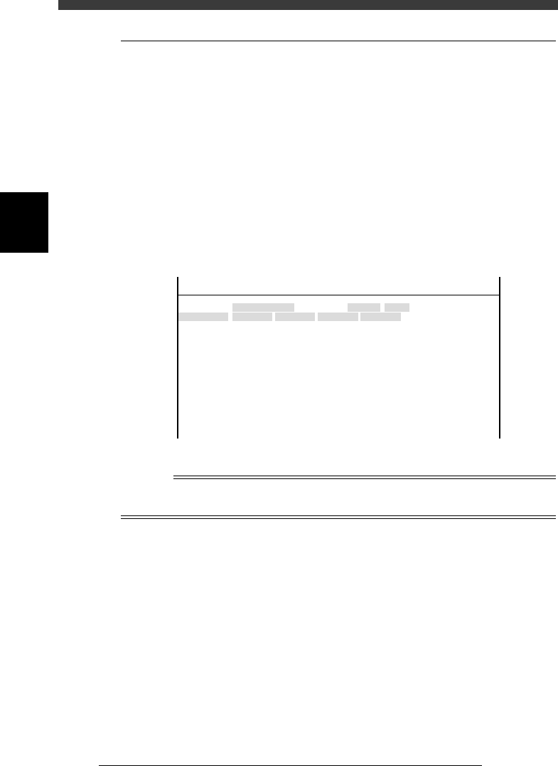
4.2 Software limits
When a servo-controlled part moves to a target position along the axis, the
software limits are used to restrict movement to avoid striking against the
mechanical stoppers at both ends of the axis. If the target position exceeds
the software limit, the error message “... AXIS SOFT LIMIT OVER”
appears and axis movement is prohibited. In MANUAL mode, the YPU
joystick can be used to move a servo-controlled part within the software
limit range.
Selecting “Software Limit” from the “Machine” submenu opens the
Software Limit screen showing the plus and minus direction software
limits of each axis and the initial position used as a reference point for axis
movement.
Software limit screen
47316-D8-00
<<<APPLICATION>>> 3/MAINTE/M
<<MODE>> 2/MCH_DATA
OBJECT
Software Limit
TCH.UNIT SPEED
- - - - - - - -
-direct.
-277.973
-272.227
-274.202
-283.200
-0.238
-0.154
-32.840
-91.717
-88.200
-26.815
-36.140
-360.000
-360.000
Init. Pos
-323.600
-321.790
-323.650
-328.650
0.000
0.000
360.271
-25.815
448.199
15.100
11.000
Init. Mov
395.000
+direct.
11.323
13.753
11.993
7.113
23.477
23.076
842.547
942.344
943.970
452.790
449.199
360.000
360.000
Axis
W1/RIGHT
W2/A-TBL
W3/B-TBL
W4/LEFT
Z1/A-TBL
Z2/B-TBL
T1/MAIN
X1/A-TBL
X2/B-TBL
Y1/A-TBL
Y2/B-TBL
R1/A-TBL
R2/B-TBL
Reference
For more details about parameters on the Software Limit screen, see “3.1 Software limits”
in Chapter 4 and “1. Adjusting the conveyor unit” in Chapter 6.
3
-19
Service Manual
Chapter 3
SED8013110
3
Machine data edit mode
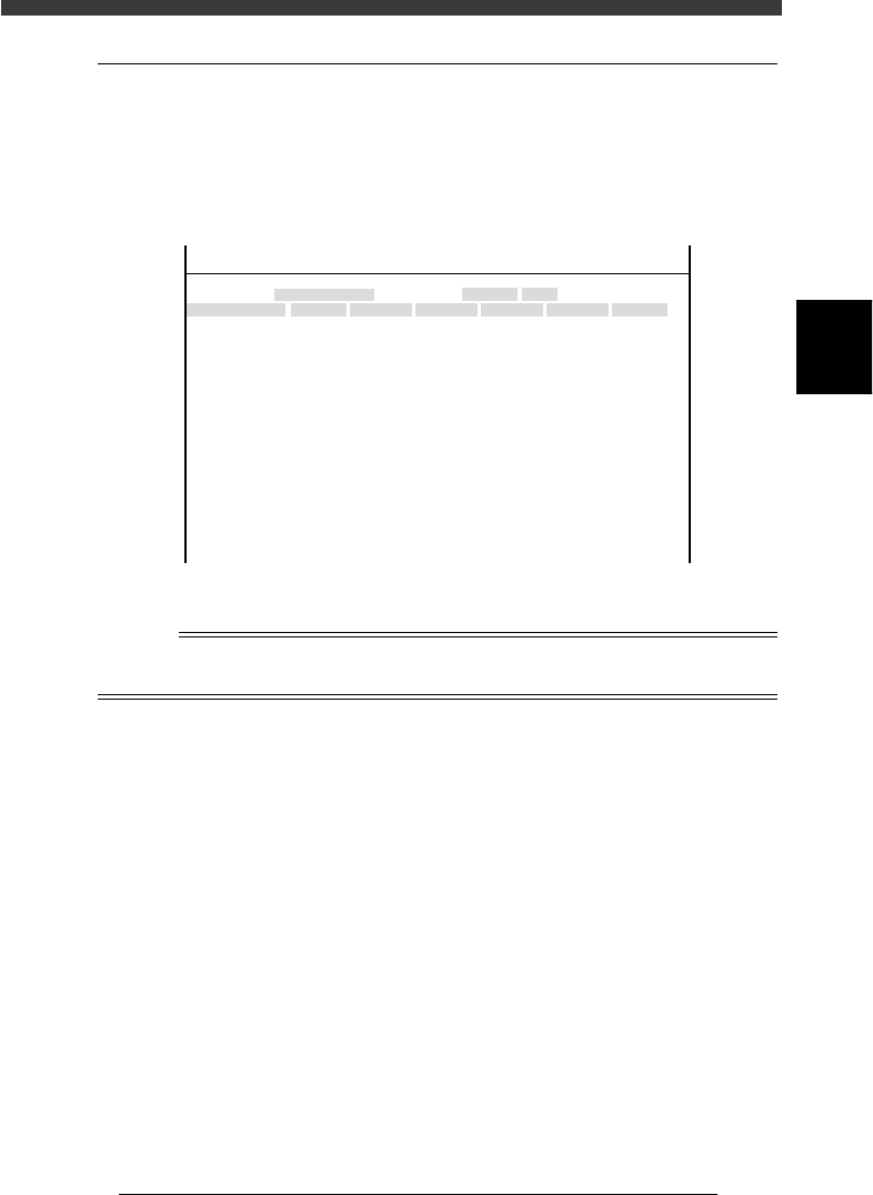
4.3 Position
Selecting “Position” from the “Machine” submenu opens the Position
screen showing the position of each hardware device versus the origin and
other basic parameter settings. On this screen, you can perform teaching or
editing of each parameter setting.
Position screen
47317-D8-00
X
-28.280
-28.280
562.000
255.916
0.500
100.000
130.000
0.000
10.000
100
-9.709
312.105
312.105
-44.554
Object
FINE mode
Locate pin
Edge Clamp
Wait point
Discard point
PCB Height
Simul. pickarea
QFP clearance
Retry Limit.
Dump station1
Dump station2
Fiducial cor.
T-axis Distance
T-axis Speed
Conv Correct1
Conv Correct2
Conv Correct3
Conv Correct4
Type
NORMAL
100
DUMP
4.00
NO RETRY
2.00
2.00
Nouse
OBJECT
Position
TCH. UNIT SPEED
- - - - - - - -
A
A
A
A
A
A
A
A
A
A
A
A
A
A
A
Y
0.005
118.810
118.810
0.000
71.321
0.5000
150.000
210.000
0.000
30
110.195
110.194
290.522
290.441
Z
0.000
0.000
17.480
0.500
16.000
16.000
0.000
10.000
20
17.438
17.460
17.493
17.512
R
0.000
0.000
0.000
0.000
17.480
0.200
0.000
10.000
Feeder
100
0
0
<<<APPLICATION>>> 3/MAINTE/M
<<MODE>> 2/MCH_DATA
Reference
For more details about parameters on the Position screen, see “3.2 Position (machine
coordinates)” in Chapter 4.
3
-20
Service Manual
Chapter 3
3
Machine data edit mode
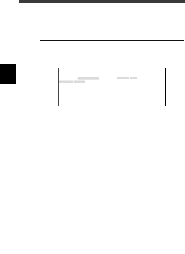
5. Other
Selecting “Other” - “RS-232C Port” shows the communication protocol
settings.
5.1 RS-232C
Communication protocols can be specified on this screen. Use the same
protocol settings as the other side to be communicated.
RS-232C protocols
47318-C0-00
Object
Time-out
CR/CRLF
Flow CTRL.
BaudRate
Parity
Stop Bit
Data Bits
Value
No
CR
XON/OFF
9600
0dd
1bit
8bits
OBJECT
RS-232C Port
TCH. UNIT SPEED
- - - - - - - -
<<<APPLICATION>>> 3/MAINTE/M
<<MODE>> 2/MCH_DATA