YV180X_Mainte_E.pdf - 第74页
4 -16 Service Manual Chapter 4 SED8013110 4 Machine adjust mode When setting the locate pin position, perform teaching at the center of the fix ed locate pin as explained belo w . 1 Raise the locate pin. 1. Select <3/…
4
-15
SED8013110
Service Manual
Chapter 4
4
Machine adjust mode
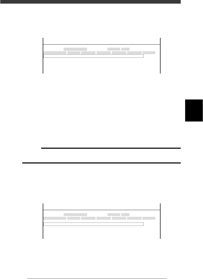
FINE mode
Accuracy for recognizing a fiducial mark with the moving camera and a
component pickup error rate for triggering an alert function are specified
here.
47411-D8-00
X
-28.280
-28.280
562.000
255.916
Object
FINE mode
Locate pin
Edge Clamp
Wait point
Discard point
Type
NORMAL
100
OBJECT
Position
TCH. UNIT SPEED
- - - - - - - -
A
A
A
A
Y
0.005
118.810
118.810
0.000
71.321
Z
0.000
0.000
R
0.000
0.000
0.000
0.000
Feeder
<<<APPLICATION>>> 3/MAINTE/M
<<MODE>> 2/MCH_DATA
Y This parameter is used to determine how accurately the mark
position should be converged (adjusted) to the specified point
during fiducial mark recognition with the moving camera.
This setting can be 0.000 to 0.100mm. Set to 0.005 in most
cases. This setting is valid only when FINE mode is selected
in the mark information.
R Component pickup error rate for issuing an alert signal. If the
pickup error rate of a component exceeds this setting during
automatic operation, an alert function is triggered for that
component.
c
CAUTION
The smaller the setting in the Y column parameter, the higher the positioning accuracy.
However, the recognition time becomes longer affecting the cycle time.
Locate pin position
This is the reference position when a PCB is clamped in the mounting
position on the conveyor.
47411-D8-A0
X
-28.280
-28.280
562.000
255.916
Object
FINE mode
Locate pin
Edge Clamp
Wait point
Discard point
Type
NORMAL
100
OBJECT
Position
TCH. UNIT SPEED
- - - - - - - -
A
A
A
A
Y
0.005
118.810
118.810
0.000
71.321
Z
0.000
0.000
R
0.000
0.000
0.000
0.000
Feeder
<<<APPLICATION>>> 3/MAINTE/M
<<MODE>> 2/MCH_DATA
X, Y XY coordinates at the center of the fixed locate pin.
R If the side of a PCB clamped in the component mounting
position is not in complete contact with the conveyor rail,
enter the offset angle here. Set to 0.00 in most cases.
4
-16
Service Manual
Chapter 4
SED8013110
4
Machine adjust mode
When setting the locate pin position, perform teaching at the center of the
fixed locate pin as explained below.
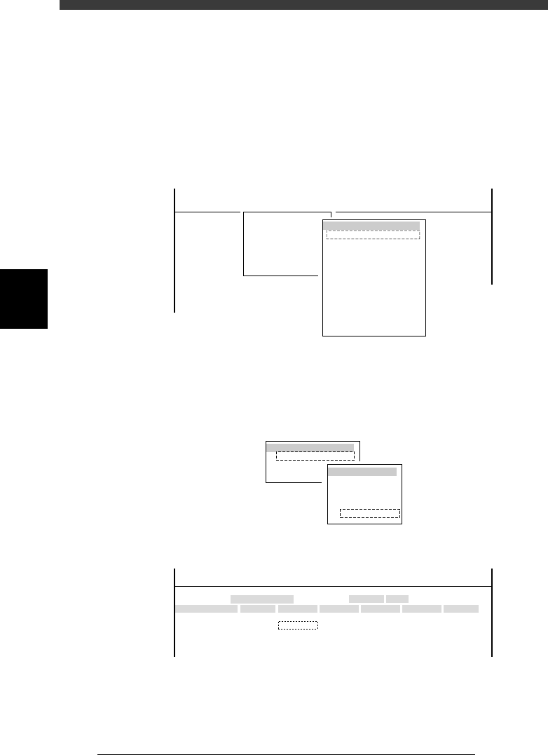
1 Raise the locate pin.
1. Select <3/4/A0 CONVEYOR UNITS> to open the CONVEYOR UNIT
menu box.
2. Use the arrow keys to line up the cursor with “LOCATE PIN” and press
the [ENTER] key to raise the locate pins.
The ON/OFF status on the right changes to “ON” when the locate pins
are raised.
47412-C0-00
(STS.)
OFF
OFF
OFF
OFF
OFF
OFF
OFF
OFF
OFF
OFF
LOCATE PIN
PUSH UP
PCB CLAMPE
EDGE CLAMP
PUSH IN
MAIN STOPPER
ENT. STOPPER
EXIT. STOPPER
CONV. MOTOR
CONV. WIDTH
PROGRAM PIN
RETURN
CONVEYOR UNIT
<<<APPLICATION>>> 3/MAINTE/M
<<MODE>> 4/MANUAL
<COMMAND_LIST> A/IO_UTILITY
A0 CHANGE SPEED
2 Open the Position screen.
Select <3/3/B1 ADJUST TARGET> - “Position” and press the [ENTER] key.
3 Press the [F10] key to set the teaching conditions.
Select “Camera” for the teaching unit and a slow speed (e.g. SPEED=20 to
40).
47413-D8-00
TEACH-UNIT SEL.
Camera
Head1
Head8
SPEED SELECT.
Speed1 =
Speed2 =
Speed3 =
Speed4 =
Speed5 =
100
80
60
40
20
4 Move the cursor to “X” in the “Locate pin” row.
47411-D8-B0
X
-28.280
-28.280
562.000
255.916
Object
FINE mode
Locate pin
Edge Clamp
Wait point
Discard point
Type
NORMAL
100
OBJECT
Position
TCH. UNIT SPEED
- - - - - - - -
A
A
A
A
Y
0.005
118.810
118.810
0.000
71.321
Z
0.000
0.000
R
0.000
0.000
0.000
0.000
Feeder
<<<APPLICATION>>> 3/MAINTE/M
<<MODE>> 2/MCH_DATA

4
-17
SED8013110
Service Manual
Chapter 4
4
Machine adjust mode
5 Align the moving camera with the center of the fixed locate
pin.
Use the YPU joystick to move the camera to a position where the center of
the fixed locate pin is exactly aligned with the cross cursor on the vision
monitor.
6 Perform teaching for the locate pin.
1. Press the [F10] key twice to perform teaching for the X coordinate.
2. Then, position the cursor on “Y” in the “Locate pin” row, and press the
[F10] key twice to perform teaching for the Y coordinate.
7 Save the settings.
Press the [ESC] key, then select <B2 SAVE DATA> or <B0 SAVE & QUIT>
and press the [ENTER] key. (To quit without saving, select <B3 RECOVER
ADJUST> or <B7 QUIT> and press the [ENTER] key.)