YV180X_Mainte_E.pdf - 第64页
4 -6 Service Manual Chapter 4 SED8013110 4 Machine adjust mode 5 Check safety , then press the [ENTER] key again. The head assembly starts to move, and the specified head picks up a component from the feeder . 6 Check th…
4
-5
SED8013110
Service Manual
Chapter 4
4
Machine adjust mode
2.2 Pickup component
<3/3/A3>
Use this command when you want to check the component pickup position
or pickup function. For example, you can check if the feeder set positions
on the feeder plate are correctly adjusted, by picking up a component from
the feeder with this command. The following steps explain the procedure
for component pickup test. Prepare in advance, a tape feeder with compo-
nents to be tested.
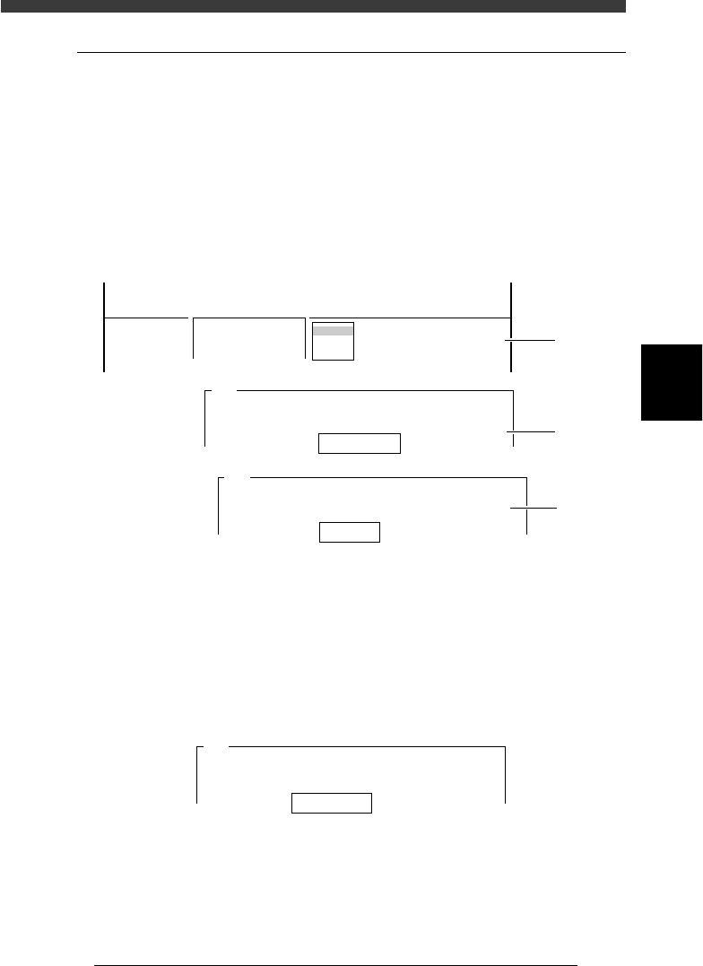
1 Run the component pickup test.
Select <3/3/A3 PICK COMPONENT> - “A table” (or “B table”) and press
the [ENTER] key.
47403-D8-00
Database No. 1
Head No. 1
A461
Please input the data base number which has already
prepared.
After input, please press the [ENTER] key.
table
A table
B table
A463
It will pick one component.
An nozzle type used by this is Type 11
Please input the head number.
<<<APPLICATION>>> 3/MAINTE/M
<<MODE>> 3/MCH_ADJUST
<COMMAND_LIST> A/UTILITY
A3 PICK COMPONENT
Step
3
Step
2
Step 1
2 Enter the database No. of the component and press the
[ENTER] key.
3 Enter the head No. and press the [ENTER] key.
Specify the head No. for which you want to perform the component
pickup test.
4 Enter the feeder set No. and press the [ENTER] key.
Specify the feeder set No. at which you have installed the tape feeder for
the component pickup test.
47404-D8-00
Feeder Set No. 10
A462
As a Tape feeder is specified by this component,
the machine can pick component automatically.
Please type feeder position number.
4
-6
Service Manual
Chapter 4
SED8013110
4
Machine adjust mode
5 Check safety, then press the [ENTER] key again.
The head assembly starts to move, and the specified head picks up a
component from the feeder.
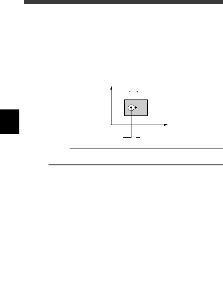
6 Check the component pickup position.
Look at the position of the nozzle tip relative to the component. (Basically,
the YV180X exhibits no positional shift in the Y direction.)
If a positional shift is found in the X direction, enter the X offset on the
FeederPlateOffset screen, as explained in the previous section “4.1 Feeder
plate offset” in Chapter 3.
Pickup position shift from component center (top view)
43401-D8-00
Center of the component
Pickup offset in
X direction
Origin
Y
X
Center of the nozzle
n
Note
If the nozzle tip has shifted to the machine origin side with respect to the center of the
component, then this is a plus offset. If shifted to the opposite side, this is a minus offset.
7 Dump the component.
Select <3/3/A4 DUMP COMPONENT> and press the [ENTER] key.
8 Check safety, then press the [ENTER] key.
The head moves to the discard point and dumps the component automati-
cally.
4
-7
SED8013110
Service Manual
Chapter 4
4
Machine adjust mode
2.3 Dump component
<3/3/A4>
To discard the component picked up by a nozzle, use the <3/3/A4 DUMP
COMPONENT> command. The head moves to the discard point specified
beforehand and discards the component there. (For details on the discard
point, see “3.2 Discard point” in this chapter.
DUMP COMPONENT command
47405-C8-00
<<<APPLICATION>>> 3/MAINTE/M
<<MODE>> 3/MCH_ADJUST
<COMMAND_LIST> A/UTILITY
A4 DUMP COMPONENT
2.4 Change nozzle
<3/3/A5>
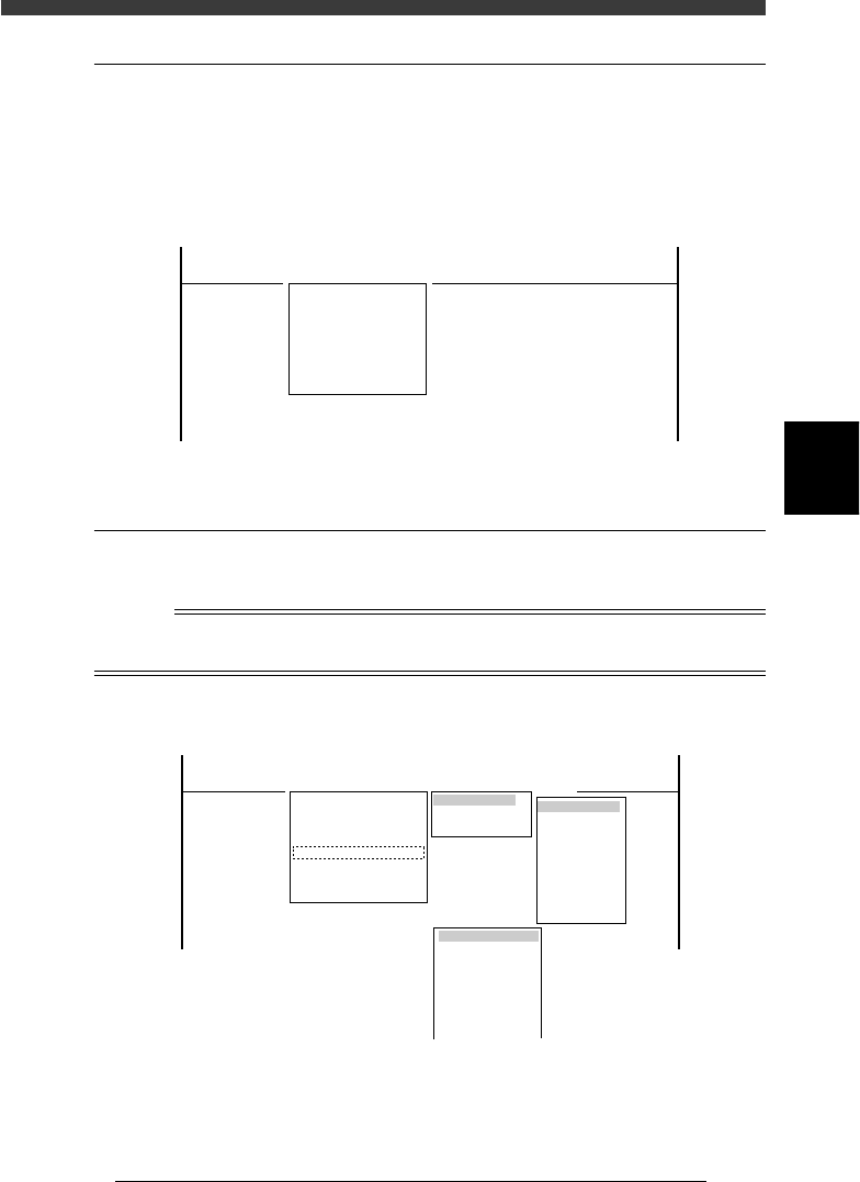
The <A5 CHANGE NOZZLE> command automatically performs nozzle
change by selecting the head and nozzle type.
Reference
The <A5 CHANGE NOZZLE> command is enabled only for Heads 2, 4, 6 and 8 which
have the FNC (flying nozzle change) function.
CHANGE NOZZLE command
47406-D8-00
Table Selection
Atable
Btable
Head Selection
Head 1
Head 2
Head 3
Head 4
Head 5
Head 6
Head 7
Head 8
SELECT NOZZLE
Type 71
Type 72
Type 73
Type 74
Type 75
Type 76
Type 77
<<<APPLICATION>>> 3/MAINTE/M
<<MODE>> 3/MCH_ADJUST
<COMMAND_LIST> A/UTILITY
A1 VACCUM ON
A2 VACCUM OFF
A3 PICK COMPONENT
A4 DUMP COMPONENT
A5 CHANGE NOZZLE
A6 HEAD DOWN VALVE
A7 CHANGE SPEED
A8 SERACH ORIGIN