YV180X_Mainte_E.pdf - 第104页
4 -46 Service Manual Chapter 4 SED8013110 4 Machine adjust mode 3. Press the [F4] key to switch to the V ision Info. sub-window and check that the Search Area parameter is set to 4.00mm. 47437-C8-00 MARK NAME Circle_D1.0…
4
-45
SED8013110
Service Manual
Chapter 4
4
Machine adjust mode
3.4.3 Calibrating the moving camera scale
The moving camera scale is a vision parameter representing a measurement
equivalent to one pixel. This scale must be calibrated correctly for accurate
recognition of PCB fiducial marks.
1 Prepare a PCB.
Prepare a PCB having a precise fiducial mark which is registered in the
database.
Reference
Use of a circular mark (for example, a 1mm diameter circular mark that uniformly
reflects light) is recommended since circular marks are generally superior in dimensional
precision to other marks. A doughnut shape is not suited for use in this adjustment.
To make more accurate adjustments, we recommend using a specially designed glass PCB
(sold separately).
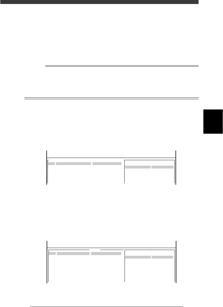
2 Open the Mark Info. screen and check the database regis-
tration No. of the mark.
1. Select <2/1/D1 SWITCH PCB DATA>, “PCB name” and “Mark Info.”,
pressing the [ENTER] key.
2. Check the database No. of the mark registered for the PCB to be used.
(When using a galss PCB, the mark database No. is 281.)
47435-C0-00
MARK NAME
Circle_D1.0
COMMENT
OBJ : Mark Info.
Mark Type Info .
Edit Term
DataBase Number
No.
1
PCB : CUK93001
<<<APPLICATION>>> 2/DATA/M
<<MODE>> 1/EDIT_DATA
:
: 153
3 Check the data registered in the mark database.
1. Select <2/3/A1 COMPONENT/MARK D.B.> - “MARK DATABASE” and
press the [ENTER] key.
2. Check the data registered in the mark database.
Check, in particular, that the mark size of the PCB exactly matches the
registered data (MarkOutSize).
(The mark on the glass PCB is 0.5mm in outer diameter.)
47436-C8-00
MARK NAME
Circle_D1.0
COMMENT
OBJ :
Vision Info.
Edit Term
Mark OutSize mm :
No.
153
<<<APPLICATION>>> 2/DATA/M
<<MODE>> 3/DATABASE
:
1.000
v
4
-46
Service Manual
Chapter 4
SED8013110
4
Machine adjust mode
3. Press the [F4] key to switch to the Vision Info. sub-window and check
that the Search Area parameter is set to 4.00mm.
47437-C8-00
MARK NAME
Circle_D1.0
COMMENT
OBJ :
Vision Info.
Edit Term
Search Area mm :
No.
153
<<<APPLICATION>>> 2/DATA/M
<<MODE>> 3/DATABASE
:
4.00
v
4 Press the [F6] key to open the Adjust Assistant screen.
The Adjust Assistant commands are used to check if the mark is clearly
recognized.
e
5 Run the FIX PCB command to clamp the PCB in place on
the conveyor.
The CONVEYOR UNIT menu box then appears, so adjust the conveyor
unit according to the size of the PCB and set the PCB on the conveyor
table. (See the mounter operation manual for how to clamp the PCB on the
conveyor table.)
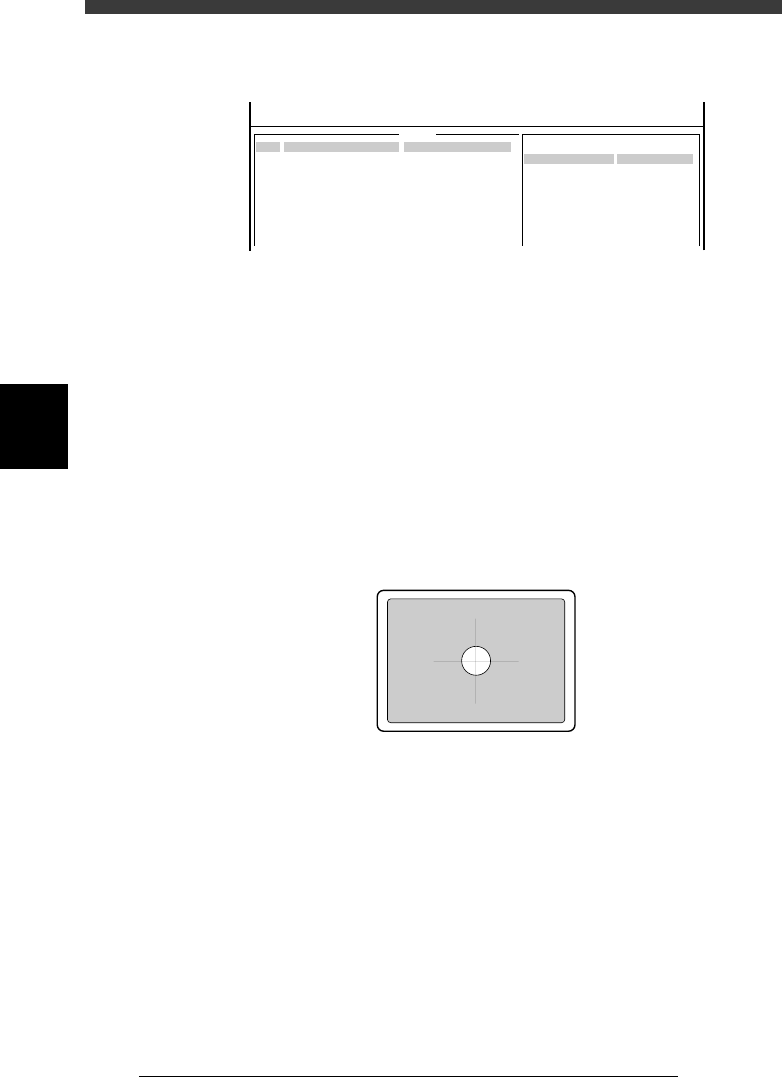
6 Cancel emergency stop, then perform teaching for the
mark position with the TEACH MARK command.
Manipulate the YPU joystick to align the center of the mark with the cross
cursor on the vision monitor.
43417-C0-00
7 Run the VISION TEST command.
When no errors occur, the current parameter settings are appropriate.
Close the Adjust Assistant mode, save the settings and advance to the next
step.
If an error occurs, use the PARAM SEARCH command to find the optimum
threshold lighting level, or adjust the moving camera lighting pattern and/
or mark information parameters as necessary. (For more details on the
parameter settings, refer to the mounter operation manual.)
4
-47
SED8013110
Service Manual
Chapter 4
4
Machine adjust mode
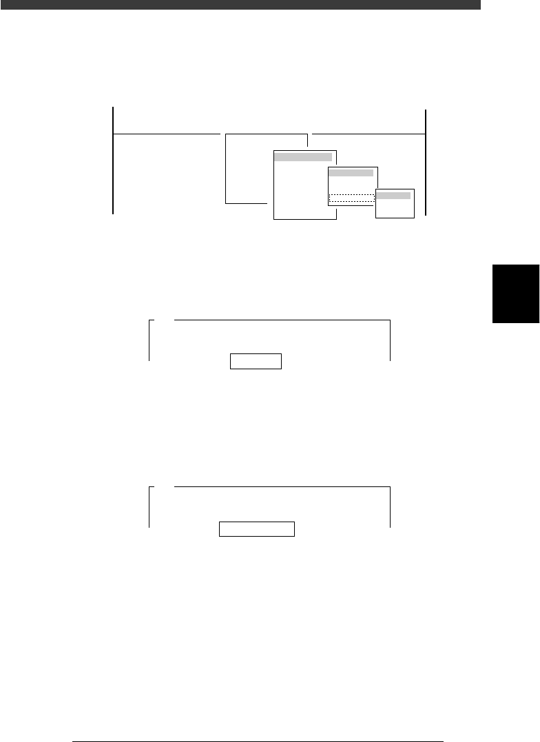
8 Enter MCH_ADJUST mode and run the “Camera Scale”
command.
Select <3/3/B1 ADJUST TARGET> − ”Moving Camera” − ”Camera Scale”
and the conveyor table.
47439-D8-00
B1 ADJUST TARGET
Object
Moving Camera
<<<APPLICATION>>> 3/MAINTE/M
<<MODE>> 3/MCH_ADJUST
<COMMAND_LIST> B/SAVE & QUIT
Target
FOV & Focus
Brightness
Camera Scale
table
A table
B table
9 Enter the mark database No. and press the [ENTER] key.
Here, enter the database No. of the mark on the PCB you are using.
(If you are using a glass PCB, enter “281”.)
47440-C0-00
Mark No. 153
A420
This procedure adjusts the vertical (Y) and horizontal (X)
scales of the moving camera. A fiducial mark is used
for this adjustment. It is recommended . . .
0 Check that “Distance (mm/10) 20” is displayed, and press
the [ENTER] key.
The camera scale is calibrated while moving the head assembly in the XY
directions. Use the default setting “20”.
47441-C0-00
Distance (mm/10) 20
A423
The axes will move and the fiducial mark will be
recognized in three different positions. Enter a
head movement distance . . .
q Clamp the PCB on the conveyor.
Use the commands in the CONVEYOR UNIT menu box that appears on
the screen.
When the PCB has already been clamped, skip this step.
w Select “RETURN” from the CONVEYOR UNIT menu box
and press the [ENTER] key.
You can also use the [ESC] key to exit the CONVEYOR UNIT menu.
If you have set emergency stop in the previous step, release the emergency
stop button and press the [READY] button.