YV180X_Mainte_E.pdf - 第81页
4 -23 SED8013110 Service Manual Chapter 4 4 Machine adjust mode 3 Open the output monitor and lower Head 1. 1. Select <3/4/A1 INPUT/OUTPUT MONIT OR> − ” SELECTION ” − ” HEAD ” and press the [ENTER] key . 2. Line up…

4
-22
Service Manual
Chapter 4
SED8013110
4
Machine adjust mode
PCB Height
This parameter indicates the height of the PCB in the component mounting
position and also specifies whether to check a nozzle after mounting or
discarding a component.
47417-D8-00
X
-28.280
-28.280
562.000
255.916
0.500
Object
FINE mode
Locate pin
Edge Clamp
Wait point
Discard point
PCB Height
Simul. pickarea
Type
NORMAL
100
DUMP
OBJECT
Position
TCH. UNIT SPEED
- - - - - - - -
A
A
A
A
A
A
Y
0.005
118.810
118.810
0.000
71.321
0.5000
Z
0.000
0.000
17.480
0.500
R
0.000
0.000
0.000
0.000
17.480
0.200
Feeder
100
<<<APPLICATION>>> 3/MAINTE/M
<<MODE>> 2/MCH_DATA
Type Specifies whether to check the nozzles during automatic
operation.
NO USE Does not make any check.
DUMPChecks a nozzle after it dumps a component.
MOUNT Checks a nozzle after it mounts a component.
R Height of the pallet of a fixed tray feeder. (This setting is
invalid for the YV180X.)
Z Height of the head assembly positioned to mount compo-
nents on a PCB.
Feeder Relative up/down speed (%) of the push-up plate. This speed
is preset to 100 (%) prior to shipping. (This setting is invalid
since the push-up plate of the YV180X moves upwards by air
pressure.)
To set the PCB height (Z coordinate), follow the steps below. Before
beginning the work, check that Type 72 nozzles are attached to all heads.
Since the height of the fixed conveyor rail surface is basically the same as
the PCB height, set it as the PCB height here.
1 Select the XY axis to move the head assembly and conveyor
table.
Select <3/4/B1 SELECT SERVO MOTOR> - ”A-table XY” (or “B-table XY)
and press the [ENTER] key.
2 Move the head assembly to above the fixed conveyor rail.
Using the YPU joystick, move the head assembly so that all heads are
positioned directly above the fixed conveyor rail.
4
-23
SED8013110
Service Manual
Chapter 4
4
Machine adjust mode
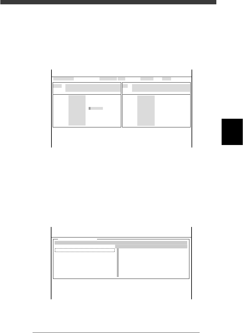
3 Open the output monitor and lower Head 1.
1. Select <3/4/A1 INPUT/OUTPUT MONITOR> − ”SELECTION” −
”HEAD” and press the [ENTER] key.
2. Line up the cursor with “T2A10” (No. 1-8 Head-A HEAD UP/DOWN)
and press the [ENTER] key to lower Head 1.
The digit changes to “1” when the head is lowered.
Output monitor screen
47414-D8-00
HEAD
HEAD
HEAD
HEAD
HEAD
HEAD
HEAD
HEAD
OUT
00000000
00000000
00000000
00000000
0
0
0
0
00000000
00000000
0
0
0
0
0
0
IN
T2A00
T2B00
T2A10
T2B10
T2A67
T2B67
T2A65
T2B65
N2230
N2330
N2223
N2323
N2216
N2316
N2214
N2314
I/O MONITOR DISP. TYPE ALL
NO 1-8 Head-A HEAD UP/DOWN
OFF 0 / ON 1
Head-A HEAD1-8 PICK JUDGMENT
PICK NG 0 / PICK OK 1
Selected Arm A_table XY
Moving Speed 40
From McahineOrigin X1= Y1= Z1= R1=
HEAD
HEAD
HEAD
HEAD
HEAD
HEAD
HEAD
HEAD
<<<APPLICATION>>> 3/MAINTE/M
<<MODE>> 4/MANUAL
OBJECT HEAD
↓↓
4 Select the ZR axis and speed.
1. Press the [SEL AXIS] key on the YPU and select “A-table ZR” (or B-table
ZR”).
2. Press the [SPEED] key on the YPU and select a slow speed below 20%.
5 Open the VACUUM SENSOR LEVEL screen.
Select <3/4/A4 VACUUM IN MONITOR> and press the [ENTER] key.
VACUUM SENSOR LEVEL screen
47415-C0-00
[ ↑ ] [ ↓ ] : Select Head [Enter]:Vaccum ON/OFF
VACCUM SENSOR LEVEL
CURRENT
0
0
0
0
0
0
0
0
MAXINMUM
0
0
0
0
0
0
0
0
MINIMUM
0
0
0
0
0
0
0
0
HEAD
A
A
A
A
A
A
A
A
From MachineOrigin X1= Y1= Z1= R1=
<<<APPLICATION>>> 3/MAINTE/M
<<MODE>> 4/MANUAL
<COMMAND_LIST> A/IO_UTILITY
[Esc]:Exit
[Space]:Freeze Display
4
-24
Service Manual
Chapter 4
SED8013110
4
Machine adjust mode
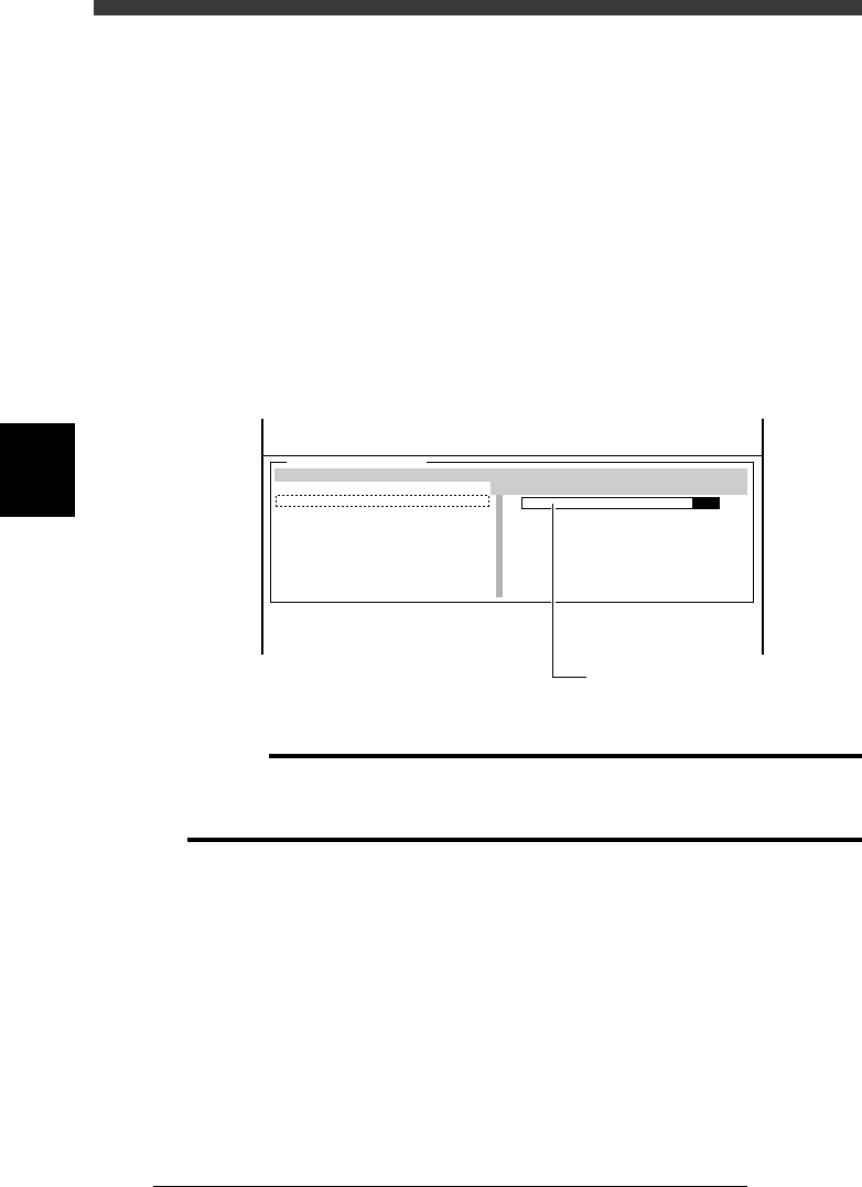
6 Generate vacuum for Head 1.
Check that the cursor is placed on the first line (Head 1) and then press the
[ENTER} key to generate a vacuum. The vacuum level bar graph appears
on the right side.
7 Lower the head assembly while checking the vacuum
sensor level and the Z coordinate.
1. Manipulate the YPU joystick to lower the head assembly.
When the nozzle tip of Head 1 reaches the surface of the conveyor rail,
the CURRENT vacuum level of Head 1 increases and the green zone of
the bar graph extends to the right.
2. Stop lowering the head assembly when the vacuum sensor level
reaches the maximum (entire bar graph turns green). The head
assembly height at this point is the PCB height, so make a note of the
Z1 (or Z2) coordinate value shown on the lower part of the operation
monitor.
47416-C0-00
[ ↑ ] [ ↓ ] : Select Head [Enter]: Vacuum ON/OFF
VACUUM SENSOR LEVEL
CURRENT
0
0
0
0
0
0
0
0
MAXIMUM
0
0
0
0
0
0
0
0
MINIMUM
0
0
0
0
0
0
0
0
HEAD
A
A
A
A
A
A
A
A
From Machine Origin X1= Y1= Z1= R1=
<<<APPLICATION>>> 3/MAINTE/M
<<MODE>> 4/MANUAL
<COMMAND_LIST> A/IO_UTILITY
[Esc]: Exit
[Space]: Freeze Display
Check the Z-axis coordinate
when the entire bar graph
turns green.
c
Caution
Type 72 nozzle is a spring-action type, so do not keep lowering the nozzle tip after the
vacuum sensor level reaches the maximum. Otherwise, the correct PCB height
coordinate cannot be measured.
8 Repeat the same procedure for other heads and calculate
the average PCB height.
9 Open the “Position” screen.
Select <3/3/B1 ADJUST TARGET> − “Position” and press the [ENTER] key.
0 Enter the “Z” coordinate of the PCB Height parameter.
Use the arrow keys to move the cursor to “Z” in the “PCB Height” row and
enter the average PCB height you calculated.
q Save the settings.
Press the [ESC] key, then select <B2 SAVE DATA> or <B0 SAVE & QUIT>
and press the [ENTER] key. (To quit without saving, select <B3 RECOVER
ADJUST> or <B7 QUIT> and press the [ENTER] key.)