YV180X_Mainte_E.pdf - 第165页
7 -11 SED8013110 Service Manual Chapter 7 7 T roubleshooting 5. Feeder 45709-C0-00 Symptom Components are not fed properly and pickup errors frequently occur. Multi-stick feeders do not function. Pickup error frequently …
7
-10
Service Manual
Chapter 7
SED8013110
7
Troubleshooting
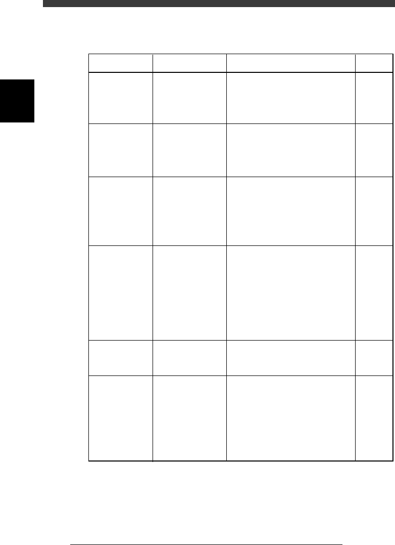
4. Conveyor
45708-C0-00
Symptom
The PCB hits
hard against the
main stopper
when it is
conveyed.
The PCB does
not reach the
main stopper
when it is
conveyed.
PCB transfer
error (PCB
clamping error)
occurs when a
thick PCB is
conveyed.
After the PCB
has been
conveyed in the
mounting
position, the
pins will not rise
to secure the
PCB. (The
conveyor keeps
turning.)
The conveyor
width cannot be
changed.
A PCB which
could be
detected before
being
transferred to
the mounting
position cannot
be detected
after transfer.
Possible cause
The soft stop does
not take effect.
The soft stop has too
much effect.
The locate pin will
not rise adequately
for a thick PCB or a
PCB having a small
reference hole, so
that the sensor
remains turned off.
The sensor at the
PCB clamping
position is defective,
or the PCB has a
cutout area just
above the sensor so
the sensor cannot
detect the PCB.
A PCB is still on the
conveyor.
The PCB is still in
the mounting
position on the
conveyor, but is not
detected with the
PCB sensor.
Corrective action
Open the front lower right panel of the
machine, and you will see the
adjustment screws for conveyor speed.
Turn the "L" screw to the left to
slightly reduce conveyor speed.
Open the front lower right panel of the
machine, and you will see the
adjustment screws for conveyor speed.
Turn the "L" screw to the right to
slightly increase conveyor speed.
Loosen the screw for the locate pin
sensor and slightly lower its position.
Then, check that the sensor turns on
when the PCB is secured in place.
Check the sensor operation in
MANUAL mode (input monitor). If
the sensor is defective, replace it. If
sensitivity seems to be low, adjust the
sensor installation height or angle.
Remove the PCB and then change the
conveyor width again.
Adjust the position of the PCB sensor
so that it detects the PCB correctly. If
the PCB still cannot be transferred
properly, check the conveyor unit
setups and/or PCB data settings and
make corrections as necessary.
Refer to
1.2 in
Chapter 6
1.2 in
Chapter 6
1.5 in
Chapter 6
1.5 in
Chapter 6
1.1 in
Chapter 6
7
-11
SED8013110
Service Manual
Chapter 7
7
Troubleshooting
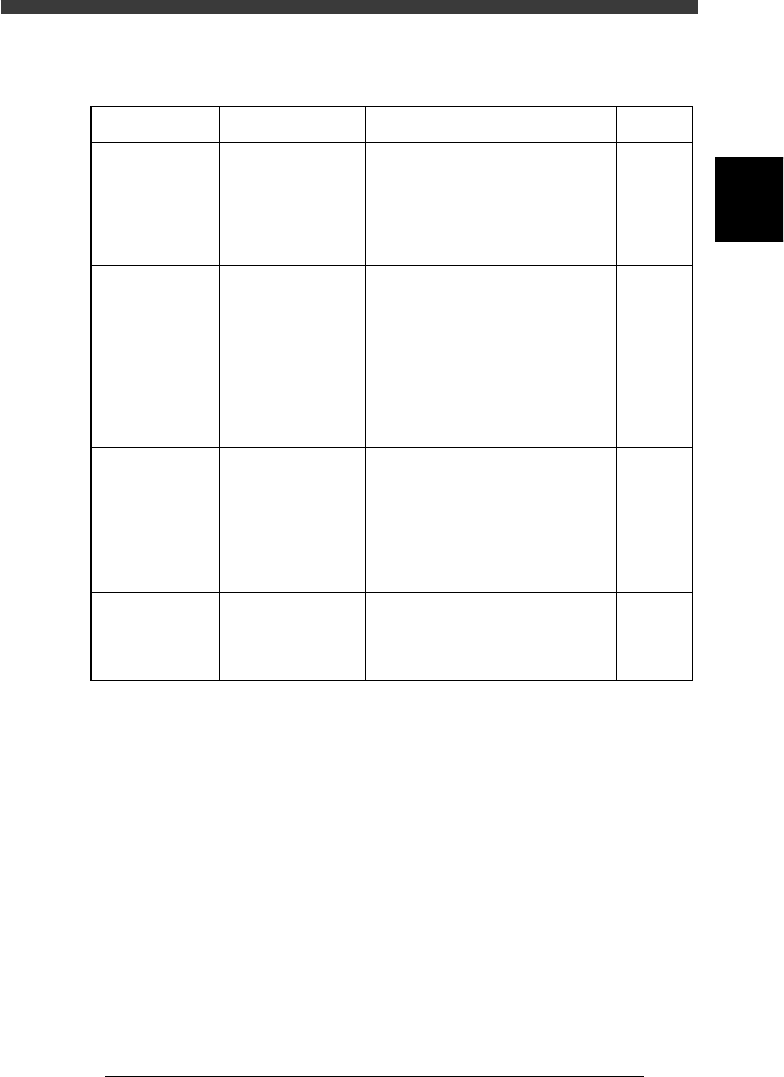
5. Feeder
45709-C0-00
Symptom
Components
are not fed
properly and
pickup errors
frequently
occur.
Multi-stick
feeders do not
function.
Pickup error
frequently
occurs with
multi-stick
feeders.
Pickup position
error occurs.
Corrective action
Correct the supply pitch for the
feeder by loosening the screws at
the air cylinder and fitting them in
the proper position.
Check that the air and power are
supplied. Set the changeover switch
to the "center" position. Also check
that the position of the positioning
pin is matched with the feeder set
No. in the Component Information.
Adjust the ascent and descent speed
to increase the speed for supplying
components. Also, check the pickup
position and correct it if necessary.
Detach the feeder from the feeder
plate and remove dust and debris.
Refer to
Feeder
user's
manual
Feeder
user's
manual
Feeder
user's
manual
Feeder
user's
manual
Possible cause
The feeder's supply
pitch is not correct.
There is a problem
with air supply,
power supply,
changeover switch,
or feeder
installation position.
Component supply
does not match the
timing that the head
picks up
components, or the
pickup position is
not correct.
Dust or debris has
intruded between
the feeder plate and
the feeder.

7
-12
Service Manual
Chapter 7
SED8013110
7
Troubleshooting
6. FNC nozzles
45710-D8-00
Symptom
The flying
nozzle position
cannot be
detected.
The specified
nozzle is not
ready for
operation.
The flying
nozzle cannot
be clamped.
Possible cause
The R-axis coordinate
for the ‘Wait point”
on the Position screen
is incorrect.
A nozzle not designed
for flying nozzle
change was selected.
The R-axis coordinate
for the ‘Wait point”
on the Position screen
is incorrect.
Corrective action
Set the R-axis coordinate of the
“Wait point” to the correct value.
Check the head No. and nozzle type
No. on the <3/1/A8 FLYING
<NOZZLE INF.> screen.
Set the R-axis coordinate of the
“Wait point” to the correct value.
Refer to
3.2 in
Chapter 4
2.6 in
Chapter 2
3.2 in
Chapter 4