YV180X_Mainte_E.pdf - 第78页
4 -20 Service Manual Chapter 4 SED8013110 4 Machine adjust mode <<Nozzle clog prevention air blow>> T o prev ent the nozzles from being clogged with dust and solder , this function is used to blo w aw ay such…
4
-19
SED8013110
Service Manual
Chapter 4
4
Machine adjust mode
When you want to change the X position of the Wait point, use the teaching
procedure as described below.
1 Open the Position screen.
Select <3/3/B1 ADJUST TARGET> −“Position” and press the [ENTER] key.
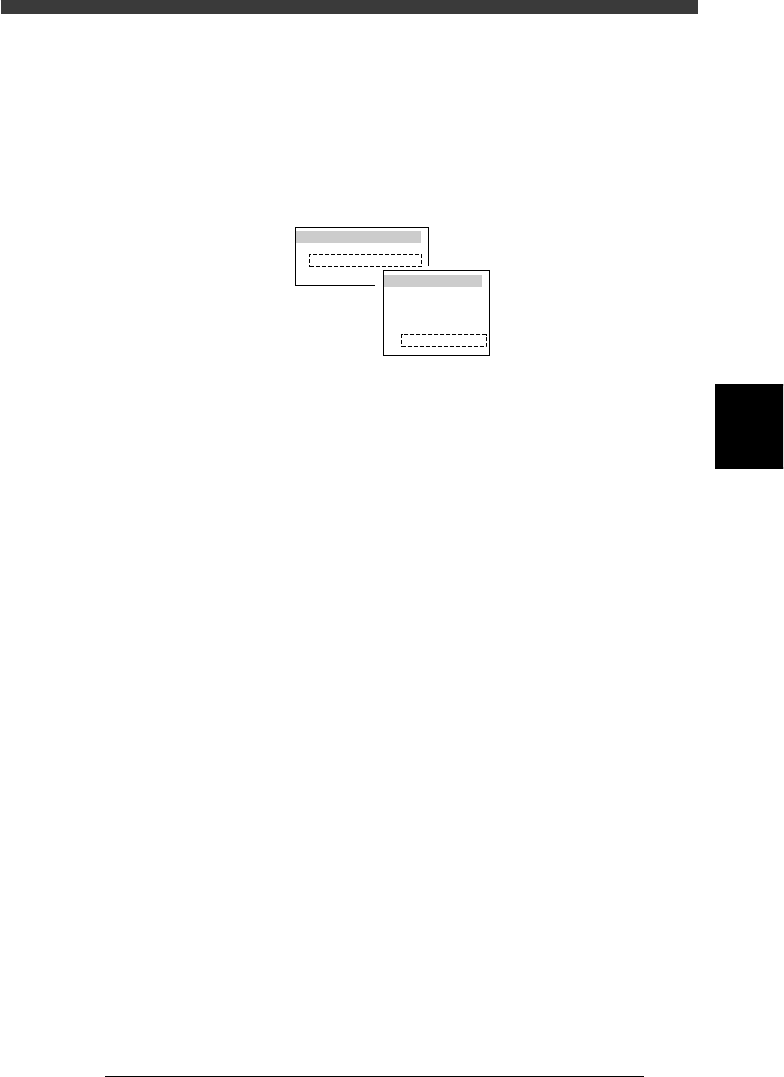
2 Press the [F10] key and specify teaching conditions.
Select “Head 1” for the teaching unit and a slow speed (e.g. SPEED=20 to
40), and press the [ENTER] key.
47413-D8-A0
TEACH-UNIT SEL.
Camera
Head1
Head8
SPEED SELECT.
Speed1 =
Speed2 =
Speed3 =
Speed4 =
Speed5 =
100
80
60
40
20
3 Line up the cursor with “X” in the “Wait point” row.
4 Move the head assembly to the desired wait point.
Manipulating the YPU joystick, move the head assembly to the desired
position.
5 Perform teaching for the wait point.
Press the [F10] key twice to perform teaching for the X coordinate of the
wait point.
6 Save the settings.
Press the [ESC] key, then select <B2 SAVE DATA> or <B0 SAVE & QUIT>
and press the [ENTER] key. (To quit without saving, select <B3 RECOVER
ADJUST> or <B7 QUIT> and press the [ENTER] key.)
4
-20
Service Manual
Chapter 4
SED8013110
4
Machine adjust mode
<<Nozzle clog prevention air blow>>
To prevent the nozzles from being clogged with dust and solder, this
function is used to blow away such foreign matter in the nozzles when the
head assembly is at the “wait point” or “discard point”. This function and
the air blow time can be specified in the Type and Feeder columns of the
Wait point and Discard point parameters.
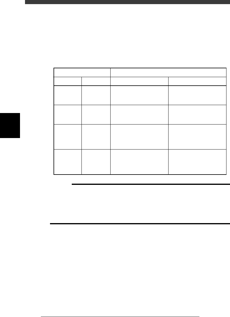
Nozzle clog prevention air blow settings and operations
45403-C0-00
OperationsSettings in “Type” column
Wait point
NORMAL
NORMAL
Discard
Discard
Discard point
NORMAL
Other than
NORMAL
NORMAL
Other than
NORMAL
At Wait point
No action
No action
Blows air for the time
specified in the Feeder
column of the Discard point.
Blows air for the time
selected in the Type column
of the Discard point.
At Discard point
Blows air for the time
specified in the Feeder
column of the Discard point.
Blows air for the time
specified in the Type column
of the Discard point.
Blows air for the time
specified in the Feeder
column of the Discard point.
Blows air for the time
specified in the Type column
of the Discard point.
c
Caution
When this air blow is performed at the “wait point”, be sure to set the “wait point” at a
position which is not above the PCB or feeder.
The setting in the Feeder column of the Discard point is shared with the air blow timer
for separating a component from the nozzle just after the component has been mounted
on the PCB. If this setting is too large, the component may bounce off the PCB at the
instant it is mounted.
4
-21
SED8013110
Service Manual
Chapter 4
4
Machine adjust mode
Discard point
This parameter specifies the discard position where each head discards a
component and air blow settings for preventing nozzle clogging.
47411-D8-E0
X
-28.280
-28.280
562.000
255.916
0.500
Object
FINE mode
Locate pin
Edge Clamp
Wait point
Discard point
PCB Height
Simul. pickarea
Type
NORMAL
100
DUMP
OBJECT
Position
TCH. UNIT SPEED
- - - - - - - -
A
A
A
A
A
A
Y
0.005
118.810
118.810
0.000
71.321
0.5000
Z
0.000
0.000
17.480
0.500
R
0.000
0.000
0.000
0.000
17.480
0.200
Feeder
100
<<<APPLICATION>>> 3/MAINTE/M
<<MODE>> 2/MCH_DATA
Type Specifies whether to perform air blow to prevent nozzle
clogging with dust or solder. See “Wait point” for more
details.
X, Y Position where Head 1 discards a component. A typical
discard point is entered at the factory prior to shipping to
match the position of the dump box. Do not change this
setting.
Z Height of the nozzles when dumping a component. A typical
height is entered at the factory prior to shipping. This is
usually “0.000” because it is not necessary to lower the
nozzles when dumping a component.
Feeder Indicates the time duration for which air blow turns on to
discard or mount a component (in milliseconds). This is valid
only for machines with an air blow unit and is typically set to
20 to 100ms.
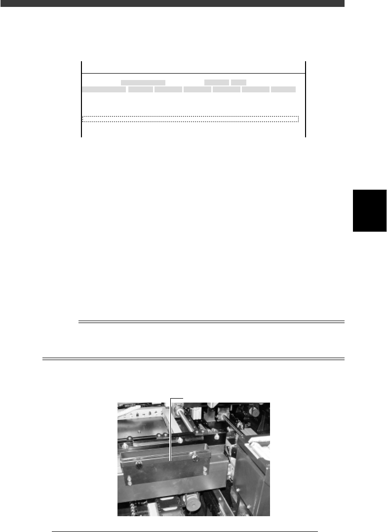
Reference
On standard YV180X, a component dump box is attached with the screws to the outside of
the fixed conveyor rail (A table) or movable conveyor rail (B table). This position cannot
be changed.
Dump box
43418-D8-00
Dump box