YV180X_Mainte_E.pdf - 第155页
6 -17 SED8013110 Service Manual Chapter 6 6 Conveyor unit and air supply unit adjustment 2.2 Pressure-dr op detection level If the air supply pressure drops belo w this le vel, the pressure-drop detec- tion switch trigge…
6
-16
Service Manual
Chapter 6
SED8013110
6
Conveyor unit and air supply unit adjustment
2. Air supply unit
The air supply unit is located inside the left side of the machine, along with
a pressure regulator. The air pressure indicator is located on the front lower
left of the machine. The pressure regulator must be set correctly in order to
provide optimum air pressure for the vacuum ejector and pneumatic
devices.
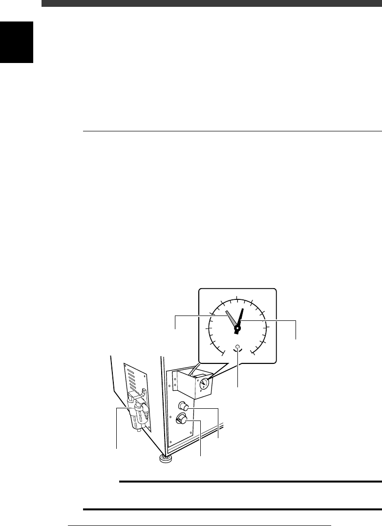
2.1 Air pressure regulator
The air pressure regulator can be adjusted with the valve control knob as
follows. Before making this setting, be sure that the pressure from the
primary air supply is between 0.6 and 0.7MPa.
1 Open the lower right panel on the front side of the
machine.
The pressure control valve knob and residual pressure bleed off knob are
located inside the panel.
2 Adjust the air pressure.
Turn the pressure control valve knob so that the air pressure (black needle)
is set at 0.55MPa.
Pressure regulator and valve control knob
43607-C0-00
0
1
2
3
4
5
6
7
8
9
10
0.0
0.1
0.2
0.3
0.4
0.5
0.6
0.7
0.8
0.9
1.0
MPa
(kgf/cm )
2
Pressure indicator
Pressure bleed off knob
Adjustment screw
(for setting pressure drop detection level)
Pressure indicator needle (black
)
Pressure drop detection level (red)
Pressure control valve knob
Pressure regulator
c
Caution
If this pressure setting is incorrect, the vacuum ejector cannot work adequately and air
cylinders become unstable. Be sure that the pressure is set at the specified value.
6
-17
SED8013110
Service Manual
Chapter 6
6
Conveyor unit and air supply unit adjustment
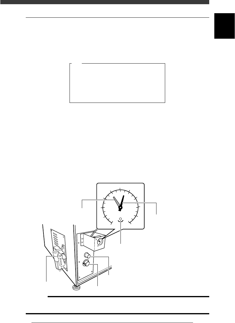
2.2 Pressure-drop detection level
If the air supply pressure drops below this level, the pressure-drop detec-
tion switch triggers emergency stop and prohibits the movement on all
axes. At the same time, the message below appears on the operation
monitor.
Pressure-drop detection
47606-C0-00
QUICK STOP ACTIVE: "NM09 AIR PRESSURE SW",
QUICK STOP FUNCTION for safety is now active.
To continue, please check the supplied air ...
E0806
1 Open the lower right panel on the front side of the
machine.
The pressure control valve knob and residual pressure bleed off knob are
located inside the panel.
2 Adjust the pressure-drop detection level (red needle
setting).
Use a small slotted screwdriver to turn the adjustment screw in the
pressure indicator on the front lower left of the machine so that the red
needle is set at 0.4MPa.
Air pressure-drop level setting
43607-C0-00
0
1
2
3
4
5
6
7
8
9
10
0.0
0.1
0.2
0.3
0.4
0.5
0.6
0.7
0.8
0.9
1.0
MPa
(kgf/cm )
2
Pressure indicator
Pressure bleed off knob
Adjustment screw
(for setting pressure drop detection level)
Pressure indicator needle (black
)
Pressure drop detection level (red)
Pressure control valve knob
Pressure regulator
c
Caution
If this setting is incorrect, the machine cannot detect abnormal pressure (pressure-drop)
in the air supply. Be sure to set this level at the specified value.

Chapter 7
Troubleshooting
1. Pickup errors 7-3
1.1 Chip components .......................................................................................7-3
1.2 QFP components .......................................................................................7-4
2. Mounting errors 7-5
2.1 Chip components .......................................................................................7-5
2.2 QFP components .......................................................................................7-6
3. Recognition errors 7-7
3.1 Chip components .......................................................................................7-7
3.2 QFP components .......................................................................................7-8
3.3 Mark ..........................................................................................................7-9
4. Conveyor 7-10
5. Feeder 7-11
6. FNC nozzles 7-12
7. Others 7-13
Chapter 7 describes possible causes and corrective action for typical
errors which may occur during daily operation.