YV180X_Mainte_E.pdf - 第99页
4 -41 SED8013110 Service Manual Chapter 4 4 Machine adjust mode 3.4.2 Adjusting the moving camera lighting level For accurate recognition of PCB fiducial marks, the lighting le vel of the moving camera must be optimized.…
4
-40
Service Manual
Chapter 4
SED8013110
4
Machine adjust mode
9 Cancel emergency stop, then move the camera to above
the conveyor rail.
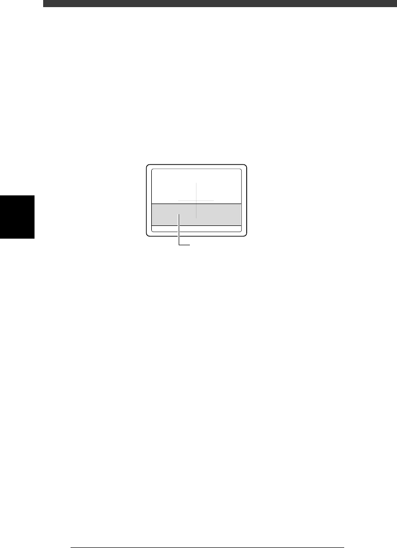
Manipulate the YPU joystick to move the camera so that the conveyor rail
is displayed near the middle of the vision monitor.
e
0 Press the emergency stop button, then adjust the camera
angle.
Rotate the camera body so that the conveyor rail is parallel to the cross
cursor on the vision monitor.
Adjustments of the moving camera focus (height), FOV and angle are now
complete.
Moving camera angle adjustment
43424-D8-00
Adjust the camera angle so that the conveyor
rail is parallel to the cross cursor.
q Tighten the two bolts to securely clamp the camera lens
tube.
Recheck the focus and angle after tightening the bolts.
w Follow the messages on the operation monitor to quit the
adjustment.
When the PCB on the conveyor table is unclamped, remove the PCB.
There is no machine data to be saved in this adjustment.
4
-41
SED8013110
Service Manual
Chapter 4
4
Machine adjust mode
3.4.2 Adjusting the moving camera lighting level
For accurate recognition of PCB fiducial marks, the lighting level of the
moving camera must be optimized. To make the adjustment, an optional
custom tool (light adjuster plate: KM1-M8806-XXX) should be used.
e
1 Press the emergency stop button and prepare the necessary
tools.
1. Using a hex wrench, remove the I/O board cover on right of the head
assembly. (See Step 10.)
2. Prepare the light adjuster plate (available from YAMAHA as an option).
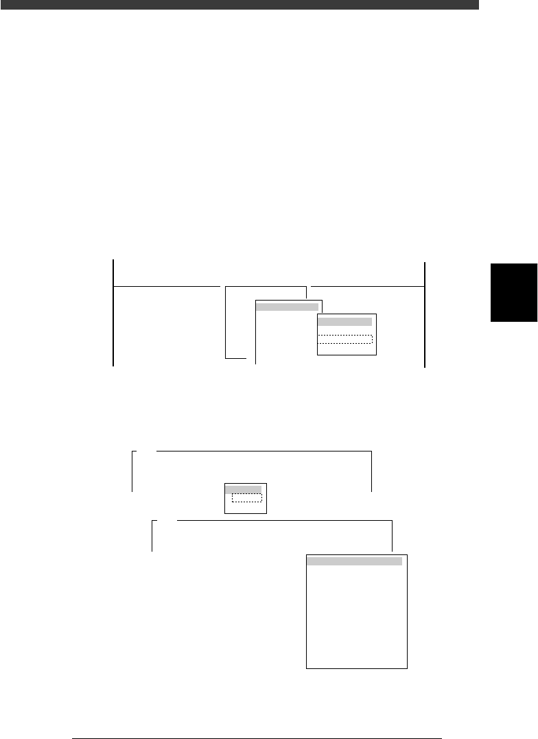
2 Run the “Moving Camera” command.
1. Select <3/3/B1 ADJUST TARGET> − ”Moving Camera” − ”Brightness”
and press the [ENTER] key.
47431-D8-00
Target
FOV & Focus
Broghtness
Camera Scale
B1 ADJUST TARGET
Object
Moving Camera
<<<APPLICATION>>> 3/MAINTE/M
<<MODE>> 3/MCH_ADJUST
<COMMAND_LIST> B/SAVE & QUIT
2. Select the conveyor table and press the [ENTER] key.
The CONVEYOR UNIT menu box then appears.
47432-D8-00
Please select table you want to adjust and press the
[ENTER] key.
To return.....
A303
Target
Atable
Btable
Please put the specified PCB at the mount position
with the conveyor unit utility, and put....
A654
LOCATE PIN
PUSH UP
PCB CLAMP
EDGE CLAMP
PUSH IN
MAIN STOPPER
ENT. STOPPER
EXIT. STOPPER
CONV. MOTOR
CONV. WIDTH
PROGRAM PIN
RETURN
CONVEYOR UNIT
4
-42
Service Manual
Chapter 4
SED8013110
4
Machine adjust mode
3 Set the light adjuster plate on the conveyor.
Set the light adjuster plate on the conveyor rail just above the fixed locate
pin, with the two-tone side facing up. Then run the PCB CLAMP command
in the CONVEYOR UNIT menu box so that the light adjuster plate is
clamped between the PCB support plate and the PCB side clamp.
43408-C0-00
Light adjuster plate
n
NOTE
As shown in the illustration below, set the dark gray edge of the light adjuster plate on the
conveyor rail just above the fixed locate pin, with the two-tone side facing up.
4 Cancel emergency stop after the light adjuster plate is
clamped on the conveyor.
Release the emergency stop button by turning it clockwise and press the
[READY] button.
5 Select “RETURN” from the CONVEYOR UNIT menu box
and press the [ENTER] key.
You can also use the [ESC] key to exit the CONVEYOR UNIT menu.
6 Check safety, then press the [ENTER] key.
The head assembly moves to above the locate pin and the teaching screen
for the light adjuster plate then appears.
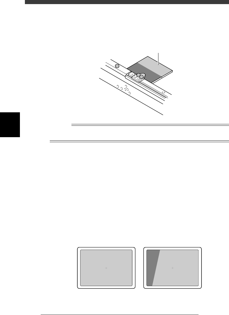
7 Adjust the camera position.
While manipulating the YPU joystick, adjust the position of the moving
camera so that the light gray area on the light adjuster plate is displayed
over the entire field of view.
43416-C0-00
OK NG