YV180X_Mainte_E.pdf - 第60页
1. Machine adjust mode main menus 4-3 2. Utility <3/3/A> 4-4 2.1 V acuum ON/OFF <3/3/A1> <3/3/A2> ....................................................... 4-4 2.2 Pickup component <3/3/A3> ........…

3
-22
Service Manual
Chapter 3
3
Machine data edit mode
MultiCam Marker screen
47320-D8-00
Coord. 1
0.000
182.000
0.000
0.000
0.000
0.000
0.000
0.000
0.000
0.000
0 000
Object
Maker 1 Offset
Maker 2 Offset
Maker Window
Cam3 Datym +
Cam3 Datym -
Cam4 Datym +
Cam4 Datym -
Cam5 Datym +
Cam5 Datym -
Cam6 Datym +
C6Dt
OBJECT
MultiCam Marker
TCH. UNIT SPEED
- - - - - - - -
A
A
A
A
A
A
A
A
A
A
A
Coord. 2
10.000
0.000
8.000
0.000
0.000
0.000
0.000
0.000
0.000
0.000
0 000
Coord. 3
0.000
0.000
0.000
0.000
-0.135
-0.138
0.000
0 000
Coord. 4
980
0.000
0.000
0.000
0.000
0.000
0.000
0.000
0 000
Option
255
<<<APPLICATION>>> 3/MAINTE/M
<<MODE>> 2/MCH_DATA
Marker Offset - Coord.1, Coord 2
XY offset of the reference marker on the head assembly, relative to Head
1.
Marker Window Window size used to recognize the reference
marker.
Cam Datum + Offset position measured by moving the reference
marker in the left-to-right direction above the
camera.
Cam Datum - Offset position measured by moving the reference
marker in the right-to-left direction above the
camera.
n
NOTE
“Cam Datum +” and “Cam Datum -” parameters can be automatically adjusted by
running the Marker command in MCH_ADUST mode.

1. Machine adjust mode main menus 4-3
2. Utility <3/3/A> 4-4
2.1 Vacuum ON/OFF <3/3/A1> <3/3/A2> .......................................................4-4
2.2 Pickup component <3/3/A3> .....................................................................4-5
2.3 Dump component <3/3/A4> ......................................................................4-7
2.4 Change nozzle <3/3/A5> ...........................................................................4-7
2.5 Head down valve <3/3/A6> .......................................................................4-8
2.6 Change speed <3/3/A7>.............................................................................4-8
2.7 Search origin <3/3/A8> ..............................................................................4-9
3. Adjust target <3/3/B1> 4-10
3.1 Software limits ......................................................................................... 4-11
3.2 Position (machine coordinates) ................................................................4-14
3.3 Pickup/mount vacuum levels ...................................................................4-33
3.3.1 Pickup vacuum level 4-33
3.3.2 Mount vacuum level 4-35
3.4 Moving camera ........................................................................................4-37
3.4.1 Adjusting the FOV & focus 4-38
3.4.2 Adjusting the moving camera lighting level 4-41
3.4.3 Calibrating the moving camera scale 4-45
3.5 Multi-vision camera .................................................................................4-50
3.5.1 Adjusting the FOV & focus 4-51
3.5.2 Adjusting the lighting level 4-55
3.5.3 Calibrating the multi-vision camera scale 4-58
3.5.4 Adjusting the dual-direction recognition offset 4-62
3.5.5 Marker4-65
3.6 R-axis accuracy offset...............................................................................4-67
4. Other commands 4-71
Chapter 4
Machine adjust mode
The machine was completely adjusted at the factory prior to ship-
ment or installation. However, if for some reason adjustments and
parameter settings are needed, refer to this chapter for correct
adjustment and data setting procedures.
4
-3
SED8013110
Service Manual
Chapter 4
4
Machine adjust mode
1.
Machine adjust mode main menus
Adjustment commands and utilities are stored in Machine Adjust mode.
When you select <3/3/ MCH_ ADJUST>, the two command menu win-
dows <A/UTILITY> and <B/SAVE & QUIT> can be selected. This
chapter explains these command menus. You can also refer to the help
message as necessary for information about each command, which appears
on the operation monitor by pressing the [F1] key.
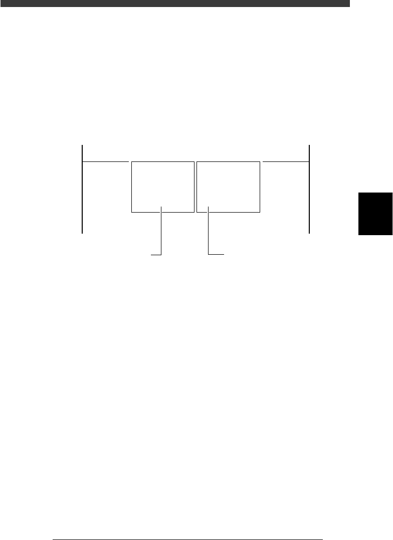
Main menu windows in Machine Adjust mode
47401-C0-00
<<<APPLICATION>>> 3/MAINTE/M
<<MODE>> 3/MCH_ADJUST
<COMMAND_LIST> A/UTILITY B/SAVE & QUIT
A1 VACUUM ON
A2 VACCUM OFF
A3 PICK COMPONENT
A4 DUMP COMPONENT
A5 CHANGE NOZZLE
A6 HEAD DOWN VALVE
A7 CHANGE SPEED
A8 SEARCH ORIGIN
B1 ADJUST TARGET
B2 SAVE DATA
B3 RECOVER ADJUST
B4 CONDITION OF TCH
B5 *
B6 **
B7 QUIT
B0 SAVE & QUIT
This menu opens when
<B/SAVE & QUIT> is selected.
This menu opens when
<A/UTILITY> is selected.