YV180X_Mainte_E.pdf - 第71页
4 -13 SED8013110 Service Manual Chapter 4 4 Machine adjust mode Axis configuration The function of each axis shown on the Softw are Limit screen is as fol- lows. Function of each axis 45402-D8-00 X1, X2 Y1, Y2 Z1, Z2 R1,…
4
-12
Service Manual
Chapter 4
SED8013110
4
Machine adjust mode
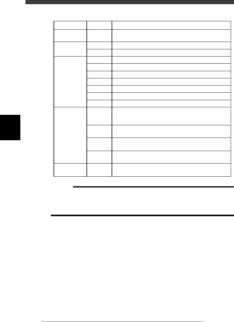
Parameter items relating to servo-controlled axes
45401-D8-00
Machine
reference
Secondary
limit
Software limit
Initial position
Initial
movement
W, Z, X,
Y, R, T
X
Y
W
Z
X (A table)
X (B table)
Y
R
T
W
Y
R
T
T
35 to 65% (See "2.7"in Chapter 4.)
1.0mm inwards from the mechanical limit
3.0mm inwards from the mechanical limit
3.0mm inwards from the mechanical limit
1.0mm inwards from the mechanical limit
1.0mm inwards from the secondary limit
1.0mm inwards from the secondary limit
3.0mm inwards from the mechanical limit
Fixed to 360˚ on the plus side and -360˚ on the minus side
5.0mm inwards from the mechanical limit
Value obtained by subtracting 0.5mm from the conveyor
width when the axis is at the origin, then expressed with
minus sign
Position at which all the A/B tables, carry-in conveyor and
carry-out conveyor are aligned straight during PCB transfer
Angle at which the nozzle holder leaf springs are parallel to
the X-axis arm.
Position at which the A-table main stopper is in contact
with the center transfer hook
This is the T-axis stroke for transferring PCBs.
Fixed to 395mm (standard machine).
SettingAxisItem
c
CAUTION
The software limits, initial positions and initial movement settings are preset at the
factory prior to shipping. It is unlikely that you will need to readjust them. If readjust-
ment is required, make correct settings while referring to the above points. For more
details, please contact YAMAHA sales office or dealer.
4
-13
SED8013110
Service Manual
Chapter 4
4
Machine adjust mode
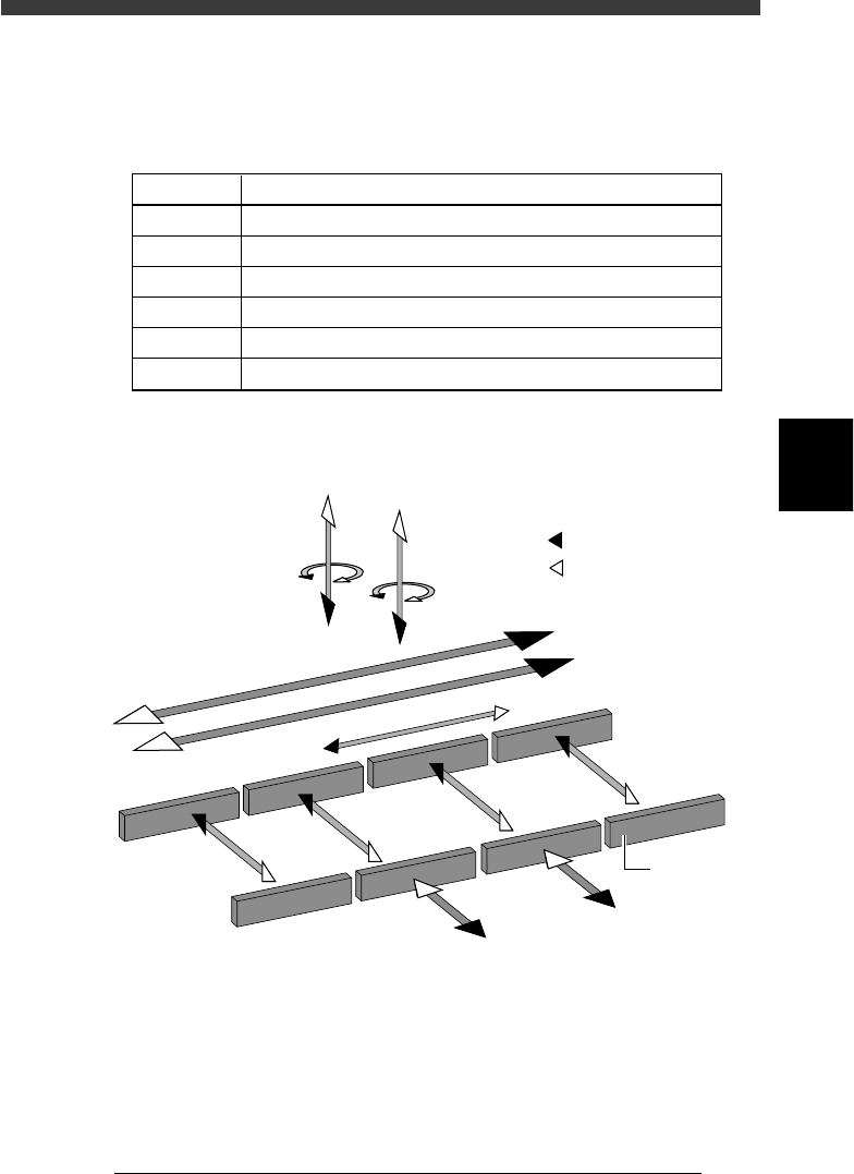
Axis configuration
The function of each axis shown on the Software Limit screen is as fol-
lows.
Function of each axis
45402-D8-00
X1, X2
Y1, Y2
Z1, Z2
R1, R2
W1 to W4
T
Axis Function
Moves the head assembly in parallel with the PCB flow.
Moves the conveyor table perpendicular to the PCB flow.
Controls the height of the head assembly.
Rotates the nozzle shafts of the head assembly.
Adjusts the conveyor width.
Transfers the PCBs on the conveyor to their next positions.
Axis configuration and plus/minus directions
43406-D8-00
W1-axis
Y2-axis
(B teble)
Y1-axis
(A table)
Z2-axis
R2-axis
Plus direction
Minus direction
X2-axis
X1-axis
T-axis
Conveyor rail
W2-axis
W3-axis
W4-axis
Z1-axis
R1-axis
4
-14
Service Manual
Chapter 4
SED8013110
4
Machine adjust mode
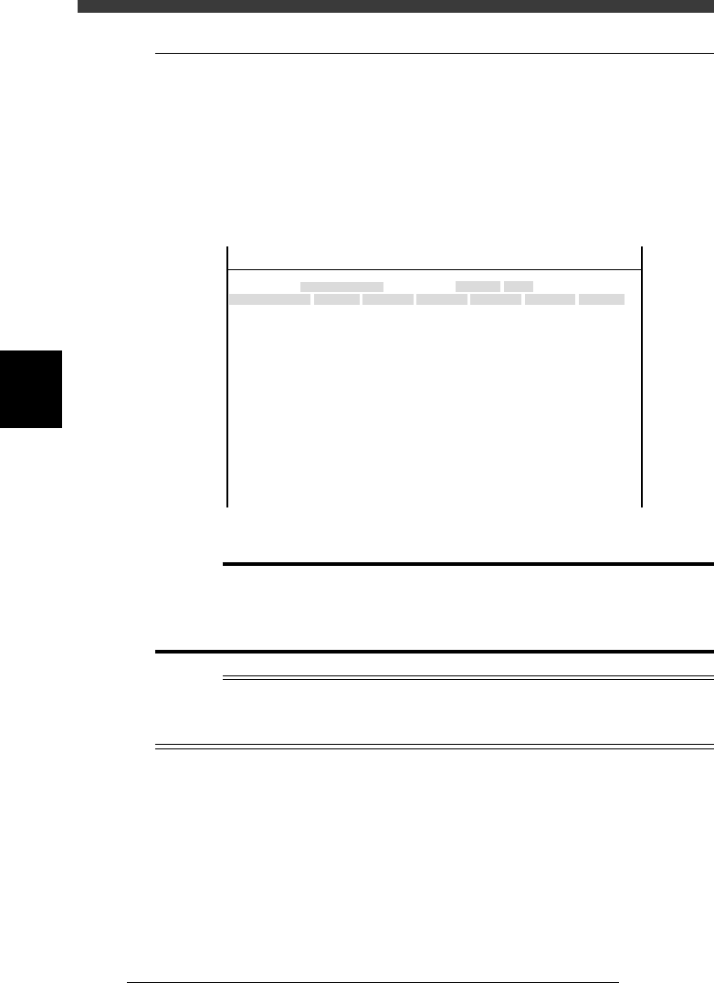
3.2 Position (machine coordinates)
When you select <3/3/B1 ADJUST TARGET> - “Position”, the following
screen appears showing the position of each hardware device relative to the
origin and other basic parameter settings. On this screen, you can perform
teaching or editing of each parameter setting. This section describes how to
set the major parameters. (Press the [F1] key and refer to the help message
displayed on the operation monitor as necessary.)
Position (machine coordinates) screen
47459-D8-00
X
-28.280
-28.280
562.000
255.916
0.500
100.000
130.000
0.000
10.000
100
-9.709
312.105
312.105
-44.554
Object
FINE mode
Locate pin
Edge Clamp
Wait point
Discard point
PCB Height
Simul. pickarea
QFP clearance
Retry Limit.
Dump station1
Dump station2
Fiducial cor.
T-axis Distance
T-axis Speed
Conv Correct1
Conv Correct2
Conv Correct3
Conv Correct4
Type
NORMAL
100
DUMP
4.00
NO RETRY
2.00
2.00
Nouse
OBJECT
Position
TCH. UNIT SPEED
- - - - - - - -
A
A
A
A
A
A
A
A
A
A
A
A
A
A
A
Y
0.005
118.810
118.810
0.000
71.321
0.5000
150.000
210.000
0.000
30
110.195
110.194
290.522
290.441
Z
0.000
0.000
17.480
0.500
16.000
16.000
0.000
10.000
20
17.438
17.460
17.493
17.512
R
0.000
0.000
0.000
0.000
17.480
0.200
0.000
10.000
Feeder
100
0
0
<<<APPLICATION>>> 3/MAINTE/M
<<MODE>> 2/MCH_DATA
c
Caution
The position data is properly adjusted at the factory prior to shipment, according to the
system to be delivered. It is unlikely that you will need to change this data. If necessary,
however, follow the procedures described in this section in order to adjust the data
correctly.
Reference
The “Position” screen opens by selecting <3/2/Machine> - “Position” in MCH_DATA
mode. (See “4.3” in Chapter 3.)
The Fiducial Cor. parameter on the Position screen is not currently used.