YV180X_Mainte_E.pdf - 第86页
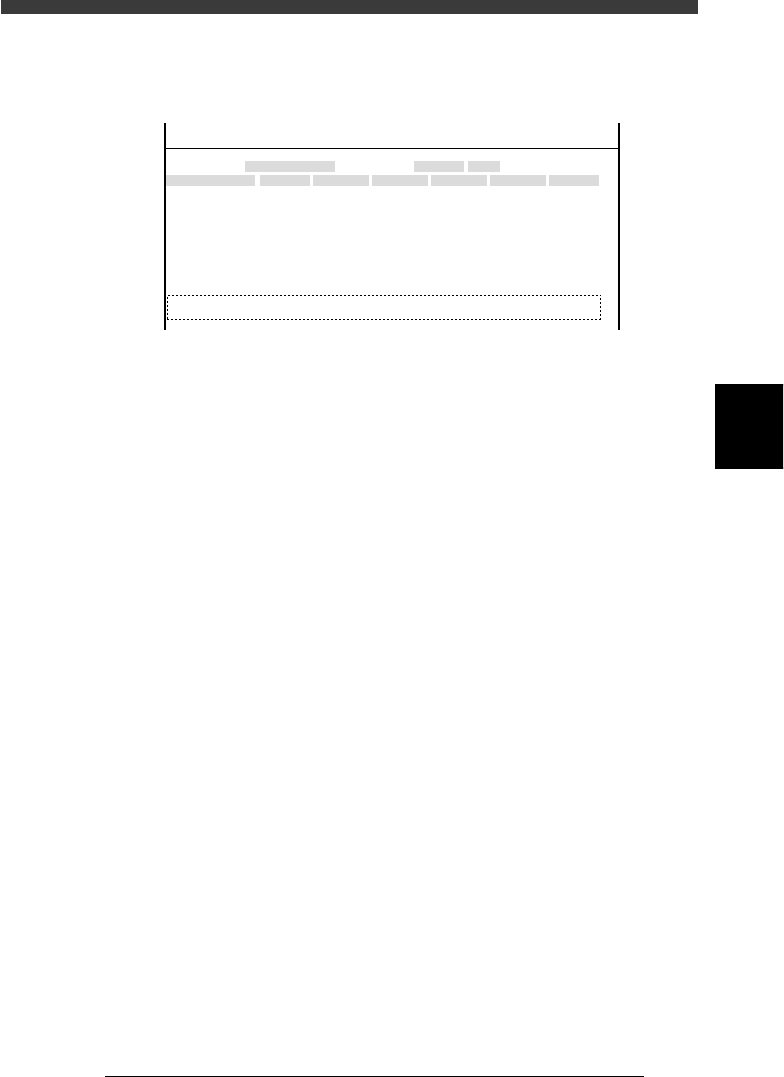
4 -28 Service Manual Chapter 4 SED8013110 4 Machine adjust mode T o set the XY and Z coordinates of a dump station, perform teaching with the steps below . e 1 Press the emergency stop button, then set the dump station o…
4
-27
SED8013110
Service Manual
Chapter 4
4
Machine adjust mode
Dump station
When an optional dump station (QFP recovery conveyor) is installed on the
feeder plate, its position coordinates must be entered here.
47420-D8-00
X
-28.280
-28.280
562.000
255.916
0.500
100.000
130.000
Object
FINE mode
Locate pin
Edge Clamp
Wait point
Discard point
PCB Height
Simul. pickarea
QFP clearance
Retry Limit.
Dump station1
Dump station2
Type
NORMAL
100
DUMP
4.00
NO RETRY
2.00
2.00
OBJECT
Position
TCH. UNIT SPEED
- - - - - - - -
A
A
A
A
A
A
A
A
A
A
Y
0.005
118.810
118.810
0.000
71.321
0.5000
150.000
210.000
Z
0.000
0.000
17.480
0.500
16.000
16.000
R
0.000
0.000
0.000
0.000
17.480
0.200
Feeder
100
0
0
<<<APPLICATION>>> 3/MAINTE/M
<<MODE>> 2/MCH_DATA
Type Time duration for which the dump station turns on to send a
dumped component to the eject position. This can be set
within a range from 0 to 2.25 seconds. Use the [INS], [DEL]
or [space] key to change the setting.
X, Y XY coordinates of the dump station installed on the feeder
plate. The dump station should be installed in a position
where all heads can reach.
Z Height (Z coordinate) of the dump station installed on the
feeder plate.
FEEDER The feeder set position number where the dump station is
installed. Because one dump station occupies a space equal
to the width of 8 standard tape feeders, this setting must be
the lowest numbered position of each feeder block consisting
of 8 feeder set positions (e.g. 1, 9, 17, 25 etc.). When no
dump station is used, set to “0”.
4
-28
Service Manual
Chapter 4
SED8013110
4
Machine adjust mode
To set the XY and Z coordinates of a dump station, perform teaching with
the steps below.
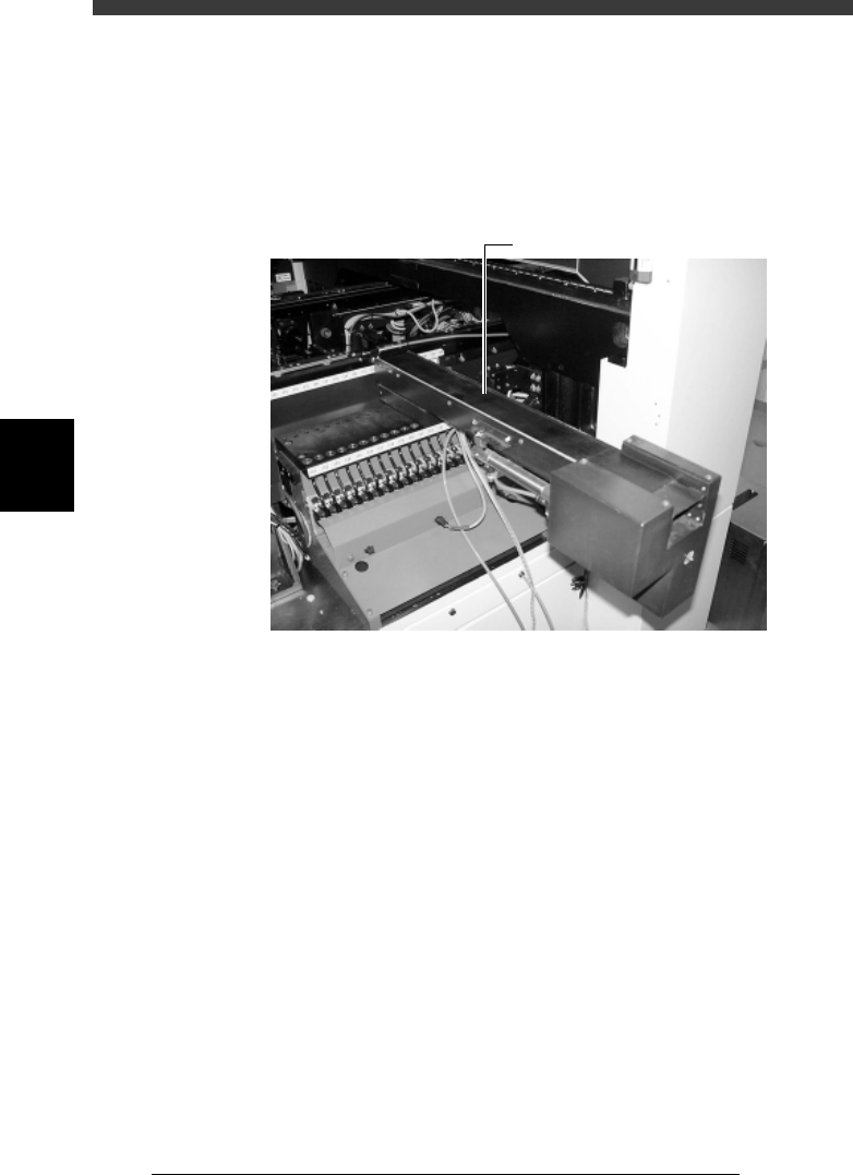
e
1 Press the emergency stop button, then set the dump station
on the feeder plate.
The dump station must be set at a position where each head can reach it.
Dump station (QFP recovery conveyor)
43419-D8-00
Dump station
2 Attach a Type 74A nozzle to Head 1.
3 Cancel emergency stop.
Ensure safety, then release the emergency stop button and press the
[READY] button.
4 Open the “Position” screen.
Select <3/3/B1 ADJUST TARGET> − ”Position” and press the [ENTER] key.
5 Press the [F10] key to set teaching conditions.
Select “Head 1” as the teaching unit and a speed (SPEED=20 to 60) and
press the [ENTER] key.
6 Position the cursor on the “X” column of the “Dump
station” row.
7 Move Head 1 to above the dump station.
Manipulate the YPU joystick to position Head 1 directly above the
component discard position on the dump station.
8 Perform teaching for the XY coordinates.
1. Press the [F10] key twice to perform teaching for the X coordinate.
2. Next, move the cursor to “Y” in the “Dump station” row.
3. Press the [F10] key twice to perform teaching for the Y coordinate.

4
-29
SED8013110
Service Manual
Chapter 4
4
Machine adjust mode
9 Move the cursor to “Z” in the “Dump station” row and
enter the Z coordinate.
Use the number keys to enter the same value as “PCB height” for the Z
coordinate.
0 Save the settings.
Press the [ESC] key, then select <B2 SAVE DATA> or <B0 SAVE & QUIT>
and press the [ENTER] key. (To quit without saving, select <B3 RECOVER
ADJUST> or <B7 QUIT> and press the [ENTER] key.)