YV180X_Mainte_E.pdf - 第28页
2 -9 SED8013110 Service Manual Chapter 2 2 Machine configuration mode SMEMA: The machine outputs a PCB request signal while a PCB carry-out request signal is input from the upstream machine. ADV ANCED GA TE: The machine …
2
-8
Service Manual
Chapter 2
SED8013110
2
Machine configuration mode
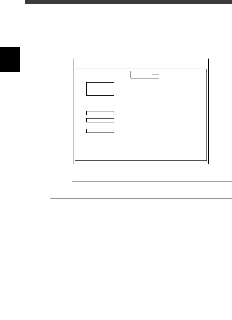
2.1.2 Detail menu in OPTION CONFIG. mode
When you place the cursor on <3/1/A1 OPTION CONFIG.> and press the
[Ctrl] + [ENTER] keys, the following detail menu window opens. You can
here check or edit more detailed option settings.
Detail menu in OPTION CONFIG. mode.
47203-D8-00
OPTION CONFIG.
(Installation)
/BASIC CONF./
/RECOGNITION/
/CONVEYOR/
/BUFFER CONV/
/TRAY CHANGER/
/OPTIONS/
Sub Machine Type
Laser Alignment
Conveyor Width Axis
Conveyor Direction
Signal handling (L)
Signal hnadling (UL)
Programmable push-up
Exit Stopper
Buffer Conveyor
Buffer Conv. W axis
Tray Changer
Ext. TC Trv. Axis
TrayChanger Pos.
Nozzle Station
Slide Feeder Bar
Co-Planarity Sensor
Dispenser Data
Dot Station
RS232C extension
Option Edit
Screen Saver
SM100XT
None
Normal
R -> L
GATE-OUT
GATE-IN
None
Exist
None
None
None
Normal
Front
None
None
None
Disappear
None
None
Exist
10 min
KM1-632312
SM-100XT
Serial :
MchType :
<<<APPLICATION>>> 3/MAINTE/M
<<MODE>> 1/MCH_CONFIG
n
NOTE
To open the detail menu window, place the cursor on <3/1/A1 OPTION CONFIG.> and
press the [Ctrl] + [ENTER] keys.
Sub Machine Type Shows the machine type. Check that this is set to
“SM180X”. Otherwise the machine will not
work correctly.
Laser Alignment This is not used in this machine. Always set to
“None”.
Conveyor Width Axis Set to “Normal” for standard machines with the
fixed conveyor rail on the front side.
Conveyor Direction Select the PCB transfer direction. Set to “R->L”
for standard machines.
Signal handling (L) Specify the type of PCB transfer signals between
this machine and the upstream machine.
GATE-OUT:
The machine outputs a PCB request signal,
but no signal is input from the upstream
machine.

2
-9
SED8013110
Service Manual
Chapter 2
2
Machine configuration mode
SMEMA:
The machine outputs a PCB request signal
while a PCB carry-out request signal is input
from the upstream machine.
ADVANCED GATE:
The machine outputs a PCB carry-in status
signal and operation status signal, while a
PCB carry-out request signal and operation
status signal are input from the upstream
machine. (Enabled only between YV-X series
machines)
Signal handling (UL) Specify the type of PCB transfer signals between
this machine and the downstream machine.
GATE-IN:
A PCB request signal is input from the
downstream machine, but no signal is
output from this machine.
SMEMA:
The machine outputs a PCB request signal
while a PCB carry-out request signal is input
from the downstream machine.
ADVANCED GATE:
The machine outputs a PCB carry-out signal
and operation status signal, while a PCB
carry-in status signal and operation status
signal are input from the downstream
machine. (Enabled only between YV-X series
machines)
Programmable Pushup This is not used in this machine. Set to “None”.
Exit Stopper Set to “Exist” for machines equipped with an exit
stopper. Set to “None when not equipped with.
Buffer Conveyor Specify the type of the buffer conveyor if
installed.
Buffer Conv. W axis Set the motor rotational direction (Normal/
Reverse) if a buffer conveyor is installed. Set to
“None” when not installed.
Tray Changer Set to “None” because the YV180X cannot be
connected to a tray changer.
Ext. TC Trv. Axis This parameter is disabled when the Tray
Changer parameter above is set to “None”.
TrayChanger Pos. This parameter is disabled when the Tray
Changer parameter above is set to “None”.
Nozzle Changer Set to “None” because the YV180X has no
nozzle station.

2
-10
Service Manual
Chapter 2
SED8013110
2
Machine configuration mode
Slide Feeder Bar Specify the type of a feeder exchange carriage if
installed.
“None”: Select this when no feeder exchange
carriage is installed.
“NonStop”: Select this when a nonstop feeder
exchange carriage is installed.
“EMG”: Select this when a feeder exchange
carriage without nonstop function is installed.
Co-Planarity Sensor Specify the position (table) of the co-planarity
sensor when installed. Set to “None” when not
installed.
Dispense Data This is only for dispenser machines. Set to
“Disappear” for the YV180X machine.
Dot Station This is only for dispenser machines with a dot
station. Set to “None” for the YV180X machine.
RS232C extension Set to “Exist” when an RS232C extension board
is installed. Set to “None” when not installed.
Option Edit Set to “Exist” when optional functions are
installed and you want to display those param-
eters in the component information and PCB
information screens in DATA Manager.
Comp. Info. Mode Standard machine should be set to “V2.0
Compatible”.
Mount Info. Mode Standard machine should be set to “V2.0
Compatible”.
Screen saver Specify the length of time until the screen saver
starts. Set to “”None” when not using the screen
saver.
MultiCam. Marker When this function is enabled, the machine
recognizes components by using the reference
marker provided on the head assembly. This
minimizes unwanted effects on recognition
accuracy from mechanical changes over time.
This function can also be selected by individual
component types in the component information.
Set to “Marker 2” when using this function with
the YV180X. Set to “NoUse” when not using this
function.
Mapping Calibration When this function is enabled, the mechanical
distortion is corrected beforehand, increasing
component mount accuracy.
Set to “Use” when using this function. Set to
“NoUse” when not using this function.
Feeder Group Specify the feeder type (FV type or CL type) to
be used with this machine.