YV180X_Mainte_E.pdf - 第112页
4 -54 Service Manual Chapter 4 SED8013110 4 Machine adjust mode q Tighten the bolts to secure the camera. e Be sure to press the emer gency stop button before this work. After tightening the bolts, recheck the focus. w F…
4
-53
SED8013110
Service Manual
Chapter 4
4
Machine adjust mode
e
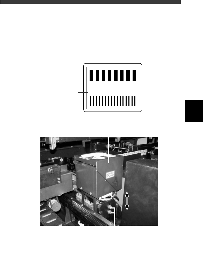
9 Press the emergency stop button and adjust the focus.
Loosen the two bolts securing the camera to the camera stand and then
adjust the camera installation height, so that the focus index value
displayed on the vision monitor is maximized. (At this point, the FOV is
set to optimum range.)
Tighten the bolts temporarily after adjusting the camera installation height.
Focus index value
43412-D8-00
4
3
2
1
0
-1
-2
-3
-3
160
Focus index
Multi-vision camera height (focus) adjustment
43423-D8-00
Multi-view camera
Loosen these bolts and move the camera upwards or downwards.
0 Cancel emergency stop and check the focus adjustment.
The image displayed on the vision monitor during this adjustment is an
image stored in the memory. It does not change as you adjust the camera
installation height. Cancel emergency stop to resume image acquisition
and check the adjustment result.
Repeat Steps 9 and 10 until the best focus is obtained.

4
-54
Service Manual
Chapter 4
SED8013110
4
Machine adjust mode
q Tighten the bolts to secure the camera.
e
Be sure to press the emergency stop button before this work. After
tightening the bolts, recheck the focus.
w Follow the message on the operation monitor to quit the
adjustment.
There is no machine data to be saved in this adjustment.
e
Remove the focus adjuster.
Be sure that the machine is in emergency stop and then remove the focus
adjuster.
4
-55
SED8013110
Service Manual
Chapter 4
4
Machine adjust mode
3.5.2 Adjusting the lighting level
To adjust the brightness level, you will need two custom tools (light
adjuster plate: KM1-M8806-0XX and light adjuster plate 2: KV7-M8806-
0XX) available from YAMAHA as options. The lighting pattern for the
multi-vision camera is divided into three zones: main, coaxial and side.
Follow the steps below to adjust the brightness in each zone.
Lighting pattern and allowable brightness range
45407-D8-00
Main
Coaxial
Side
Brightness in the light gray area on the two-tone side of
light adjuster plate (KM1-M8806-0XX)
Average brightness on the white side of light adjuster plate
(KM1-M8806-0XX)
Average brightness on the white side of light adjuster plate 2
(KV7-M8806-0XX)
Lighting
pattern
Brightness to be checked
Brightness
range
125 to 131
18 to 22
61 to 67
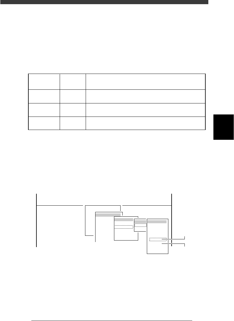
1 Run the “Multi Camera” − ”Brightness” command.
1. Select <3/3/B1 ADJUST TARGET> − ”Multi Camera” − “Brightness” and
press the [ENTER] key.
2. Select the conveyor table and the camera No. by pressing the [ENTER]
key.
The A-table multi-vision camera is designated “Cam. 5” and the B-table
multi-vision camera “Cam. 6”.
47445-D8-A0
B1 ADJUST TARGET
Object
Multi Camera
<<<APPLICATION>>> 3/MAINTE/M
<<MODE>> 3/MCH_ADJUST
<COMMAND_LIST> B/SAVE & QUIT
Target
FOV & Focus
Brightness
Camera Scale
Dual Recognition
Marker
table
A table
B table
Target
Cam. 1
Cam. 2
Cam. 3
Cam. 4
Cam. 5
Cam. 6
Cam. 7
Cam. 8
A Table
Multi Camera
B Table
Multi Camera
2 Check safety and press the [ENTER] key.
The head assembly moves to the component pickup point.