YV180X_Mainte_E.pdf - 第150页
6 -12 Service Manual Chapter 6 SED8013110 6 Conveyor unit and air supply unit adjustment 6 Save the settings. Press the [ESC] key , then select <B2 SAVE DA T A> or <B0 SA VE & QUIT> and press the [ENTER] …
6
-11
SED8013110
Service Manual
Chapter 6
6
Conveyor unit and air supply unit adjustment
1.5 Y-axis (A/B table) initial position
For smooth PCB transfer, the carry-in conveyor, A/B tables and carry-out
conveyor must be aligned straight. To ensure this, the initial position of the
Y-axis (A/B tables) is specified on the Soft Limit screen. If resetting
becomes necessary, use the following procedure.
1 Perform return-to-origin.
e
2 Press the emergency stop button.
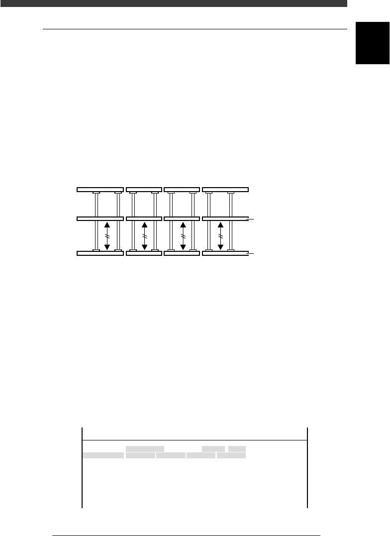
3 Align the conveyor rails.
Move the A and B tables by hand to align them with the carry-in and
carry-out conveyors, so that the fixed conveyor rails are all lined up
straight.
Conveyor rails during PCB transfer
43609-D8-00
Movable conveyor rai
l
Fixed conveyor rail
4 Open the software limit screen.
Select <3/3/B1 ADJUST TARGET> - ”Soft. Limit” and press the [ENTER]
key.
5 Enter the Y-axis initial positions.
1. Use the arrow keys to line up the cursor with “Init.Pos” in the “Y1/A-
TBL” row.
2. Press the [F10] key and set the teaching conditions.
Select any teaching unit and speed in this case.
3. Press the [F10] key twice to enter the Y1-axis initial position.
4. Next, move the cursor to “Init.Pos” in the “Y1/B-TBL” row and press the
[F10] key twice to enter the Y2-axis initial position.
Y-axis initial position setting
47607-D8-00
Axis
Y1/A-TBL
Y2/B-TBL
+direct.
452.790
449.199
OBJECT
Software Limit
TCH.UNIT SPEED
- - - - - - - -
-direct.
-26.815
-36.140
Inir.Pos
-25.815
448.199
Init.Mov
<<<APPLICATION>>> 3/MAINTE/M
<<MODE>> 3/MCH_ADJUST

6
-12
Service Manual
Chapter 6
SED8013110
6
Conveyor unit and air supply unit adjustment
6 Save the settings.
Press the [ESC] key, then select <B2 SAVE DATA> or <B0 SAVE & QUIT>
and press the [ENTER] key. (To quit without saving, select <B3 RECOVER
ADJUST> or <B7 QUIT> and press the [ENTER] key.
6
-13
SED8013110
Service Manual
Chapter 6
6
Conveyor unit and air supply unit adjustment
1.6 PCB detection sensors
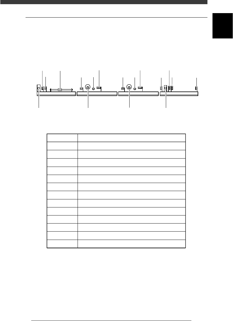
There are 10 PCB detection sensors arranged along the front rail of the
conveyor. The sensors each have LEDs mounted on the side, which are
normally lit. When the sensor detects the presence of a PCB, the LED turns
off.
PCB detection sensors (right-to-left flow)
43605-D8-00
N1034 N1150
N1154
N1031 N1030
N1033
N1032
N1035
N1036
N1153
N1050
N1054N1053
Carry-out
conveyor (W4)
Exit stopper A table
main stopper
A table
conveyor (W3)
B table
main stopper
B table
conveyor (W2)
Entrance
stopper
Carry-in
conveyor (W1)
45601-D8-00
Sensor Code Sensor Function
N1030
N1031
N1032
N1033
N1054
N1050
N1053
N1154
N1150
N1153
N1034
N1035
N1036
PCB detection at entrance of carry -in conveyor
For carry-in conveyor speed reduction
PCB detection at standby position of carry-in conveyor
PCB detection at exit of carry-in conveyor
PCB detection at B-table clamping position 1
PCB detection at B-table clamping position 2
PCB detection at exit of B-table conveyor
PCB detection at A-table clamping position 1
PCB detection at A-table clamping position 2
PCB detection at exit of A-table conveyor
PCB detection at entrance of carry-out conveyor
For carry-out conveyor speed reduction
PCB detection at exit of carry-out conveyor