YV180X_Mainte_E.pdf - 第102页
4 -44 Service Manual Chapter 4 SED8013110 4 Machine adjust mode q Press the [ESC] key to quit the adjustment. There is no machine data to be saved in this adjustment. w Remove the light adjuster plate. By following the m…
4
-43
SED8013110
Service Manual
Chapter 4
4
Machine adjust mode
8 Press the [ENTER] key when the camera is positioned.
The Adjusting Method selection box then appears.
9 Select “Use Standard Value” and press the [ENTER] key.
47434-C0-00
Adjusting Method
Use Standard Value
Manual Input
Select lighting intensity value · · ·
A667
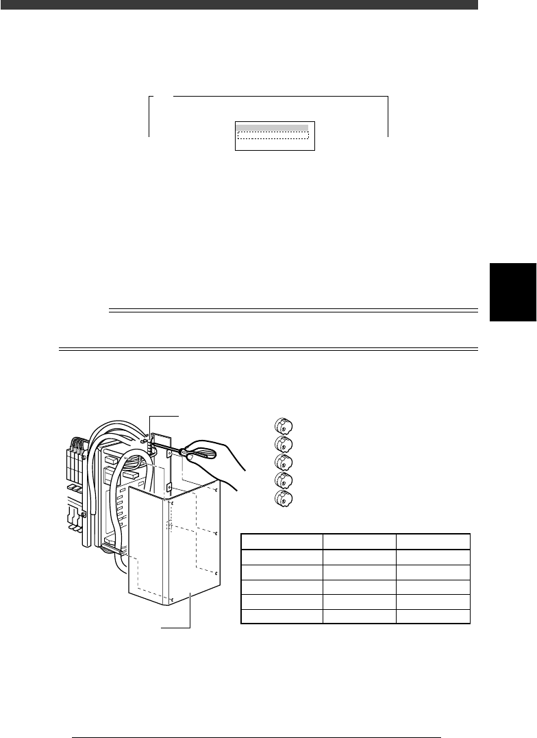
0 Press the emergency stop button, then adjust the moving
camera lighting level.
1. First adjust the LED trimmer VR1 on the I/O board.
By following the message displayed on the operation monitor, adjust
the LED trimmer VR1 so that the ”AveGrayLevel” value displayed at the
upper right of the screen matches the optimum level (30±1) shown in
the table below.
2. Adjust the LED trimmers VR2 to VR5 in the same way to set the
optimum levels.
n
NOTE
The LED trimmers VR1 to VR5 are arrayed from the top and their light levels increase by
turning the trimmer to the right (clockwise) and decrease by turning it to the left.
Moving camera lighting level adjustment
43409-D8-00
VR1
VR2
VR3
VR4
VR5
LED trimmer
I /O board cover
LED Trimmer
VR1
VR2
VR3
VR4
VR5
Lighting Zone
White-Outer
White-Inner
White-Coaxial
IR-Outer
IR-Inner
Optimum Level
30±1
30±1
12±1
30±1
30±1

4
-44
Service Manual
Chapter 4
SED8013110
4
Machine adjust mode
q Press the [ESC] key to quit the adjustment.
There is no machine data to be saved in this adjustment.
w Remove the light adjuster plate.
By following the message displayed on the operation monitor, unclamp
the PCB and then remove the PCB.
4
-45
SED8013110
Service Manual
Chapter 4
4
Machine adjust mode
3.4.3 Calibrating the moving camera scale
The moving camera scale is a vision parameter representing a measurement
equivalent to one pixel. This scale must be calibrated correctly for accurate
recognition of PCB fiducial marks.
1 Prepare a PCB.
Prepare a PCB having a precise fiducial mark which is registered in the
database.
Reference
Use of a circular mark (for example, a 1mm diameter circular mark that uniformly
reflects light) is recommended since circular marks are generally superior in dimensional
precision to other marks. A doughnut shape is not suited for use in this adjustment.
To make more accurate adjustments, we recommend using a specially designed glass PCB
(sold separately).
2 Open the Mark Info. screen and check the database regis-
tration No. of the mark.
1. Select <2/1/D1 SWITCH PCB DATA>, “PCB name” and “Mark Info.”,
pressing the [ENTER] key.
2. Check the database No. of the mark registered for the PCB to be used.
(When using a galss PCB, the mark database No. is 281.)
47435-C0-00
MARK NAME
Circle_D1.0
COMMENT
OBJ : Mark Info.
Mark Type Info .
Edit Term
DataBase Number
No.
1
PCB : CUK93001
<<<APPLICATION>>> 2/DATA/M
<<MODE>> 1/EDIT_DATA
:
: 153
3 Check the data registered in the mark database.
1. Select <2/3/A1 COMPONENT/MARK D.B.> - “MARK DATABASE” and
press the [ENTER] key.
2. Check the data registered in the mark database.
Check, in particular, that the mark size of the PCB exactly matches the
registered data (MarkOutSize).
(The mark on the glass PCB is 0.5mm in outer diameter.)
47436-C8-00
MARK NAME
Circle_D1.0
COMMENT
OBJ :
Vision Info.
Edit Term
Mark OutSize mm :
No.
153
<<<APPLICATION>>> 2/DATA/M
<<MODE>> 3/DATABASE
:
1.000
v