YV180X_Mainte_E.pdf - 第90页
4 -32 Service Manual Chapter 4 SED8013110 4 Machine adjust mode Con v . Correct 1 to 4 These parameters are used to correct the con veyor surface for non-flatness (unev en height with position). The positions (XY) at 4 p…

4
-31
SED8013110
Service Manual
Chapter 4
4
Machine adjust mode
T-axis Speed
This parameter specifies the PCB transfer hook (T-axis) movement speeds
during automatic operation.
47421-D8-A0
X
-28.280
-28.280
562.000
255.916
0.500
100.000
130.000
0.000
10.000
100
Object
FINE mode
Locate pin
Edge Clamp
Wait point
Discard point
PCB Height
Simul. pickarea
QFP clearance
Retry Limit.
Dump station1
Dump station2
Fiducial cor.
T-axis Distance
T-axis Speed
Type
NORMAL
100
DUMP
4.00
NO RETRY
2.00
2.00
Nouse
OBJECT
Position
TCH. UNIT SPEED
- - - - - - - -
A
A
A
A
A
A
A
A
A
A
A
Y
0.005
118.810
118.810
0.000
71.321
0.5000
150.000
210.000
0.000
30
Z
0.000
0.000
17.480
0.500
16.000
16.000
0.000
10.000
20
R
0.000
0.000
0.000
0.000
17.480
0.200
0.000
10.000
Feeder
100
0
0
<<<APPLICATION>>> 3/MAINTE/M
<<MODE>> 2/MCH_DATA
X Speed at which the PCB transfer hook moves back to the PCB
transfer start position and moves away from the PCB after it
has been clamped on the conveyor table.
Y1 Higher speed at which the PCB transfer hook carries the PCB.
This setting can be from 10 to 100%.
Z Lower speed at which the PCB transfer hook carries the PCB.
This setting can be from 10 to 100%.
4
-32
Service Manual
Chapter 4
SED8013110
4
Machine adjust mode
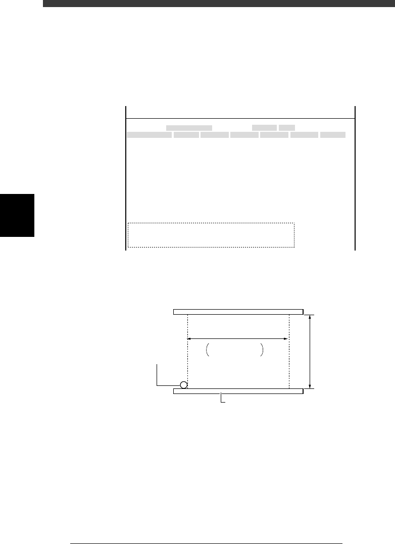
Conv. Correct 1 to 4
These parameters are used to correct the conveyor surface for non-flatness
(uneven height with position). The positions (XY) at 4 points on the
conveyor table (see below) and their heights (Z) are entered here, with the
conveyor rails widened to its maximum. To re-enter these coordinates, refer
to the teaching procedure for PCB height.
47422-D8-00
X
-28.280
-28.280
562.000
255.916
0.500
100.000
130.000
0.000
10.000
100
-9.709
312.105
312.105
-44.554
Object
FINE mode
Locate pin
Edge Clamp
Wait point
Discard point
PCB Height
Simul. pickarea
QFP clearance
Retry Limit.
Dump station1
Dump station2
Fiducial cor.
T-axis Distance
T-axis Speed
Conv Correct1
Conv Correct2
Conv Correct3
Conv Correct4
Type
NORMAL
100
DUMP
4.00
NO RETRY
2.00
2.00
Nouse
OBJECT
Position
TCH. UNIT SPEED
- - - - - - - -
A
A
A
A
A
A
A
A
A
A
A
A
A
A
A
Y
0.005
118.810
118.810
0.000
71.321
0.5000
150.000
210.000
0.000
30
110.195
110.194
290.522
290.441
Z
0.000
0.000
17.480
0.500
16.000
16.000
0.000
10.000
20
17.438
17.460
17.493
17.512
R
0.000
0.000
0.000
0.000
17.480
0.200
0.000
10.000
Feeder
100
0
0
<<<APPLICATION>>> 3/MAINTE/M
<<MODE>> 2/MCH_DATA
Conveyor height correction points
43407-D8-00
++
++
M type: 330mm
L type: 380mm
Main stopper
Maximum PCB length
Maximum
PCB widt
h
Conveyor rail
43
1
2
1 - 4:Teaching points
4
-33
SED8013110
Service Manual
Chapter 4
4
Machine adjust mode
3.3 Pickup/mount vacuum levels
3.3.1 Pickup vacuum level
When a nozzle descends and picks up a component, no air is allowed to
enter the nozzle so the vacuum pressure sensor detects a higher negative
pressure. When this detected level becomes higher than the preset pickup
vacuum level, the machine determines that the nozzle has picked up a
component. (There are other parameters the machine uses to check compo-
nent pickup.)
The pickup vacuum level should be preset for each head or nozzle, for a
level slightly higher (offset value: 5) than the minimum vacuum level
maintained when the nozzle is open (no component at the nozzle).
When measuring the vacuum level by selecting “All Nozzle Common” (see
step 1), attach Type 72 nozzles to all heads in advance.
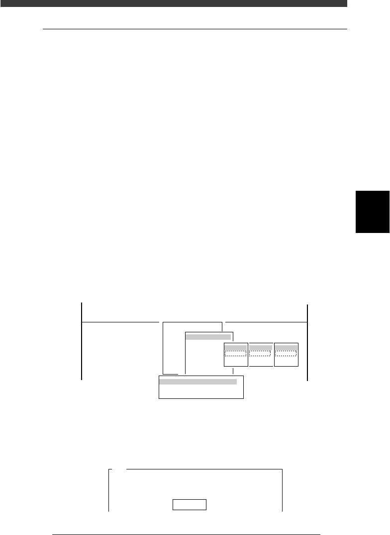
1 Run the Vacuum Level command.
1. Select <3/3/B1 ADJUST TARGET> − ”Vacuum Level” and press the
[ENTER] key.
2. Select “Each Nozzle” or “All Nozzle Common” and press the [ENTER]
key.
3. Select A table” (or “B table”) − “ALL” − ”Pick” and press the [ENTER]
key.
47423-D8-00
B1 ADJUST TARGET
Object
Vacuum Level
<<<APPLICATION>>> 3/MAINTE/M
<<MODE>> 3/MCH_ADJUST
<COMMAND_LIST> B/SAVE & QUIT
tabale
Atable
Btable
Head
ALL
Key in
Target
Pick
Mount
Vaccum Level Measuring Way
Each Nozzle
All Nozzle Common
2 Confirm that [offset 5] is displayed, and press the [ENTER]
key.
An offset of “5” is recommended.
47424-C0-00
A441
Please enter the vaccum level offset value.
The picking vaccum level equals the vaccum level when
the nozzle is......
Offset 5