YV180X_Mainte_E.pdf - 第171页
8 -5 SED8013110 Service Manual Chapter 8 8 Power and machine connections 1.3 Breaker The circuit breaker and protectors are located as sho wn below . Breakers 43804-C0-00 QF11 QF22 QF31 QF32 QF21 QF23 QF24 QF1 1: Main br…
8
-4
Service Manual
Chapter 8
SED8013110
8
Power and machine connections
1.2 Power connections
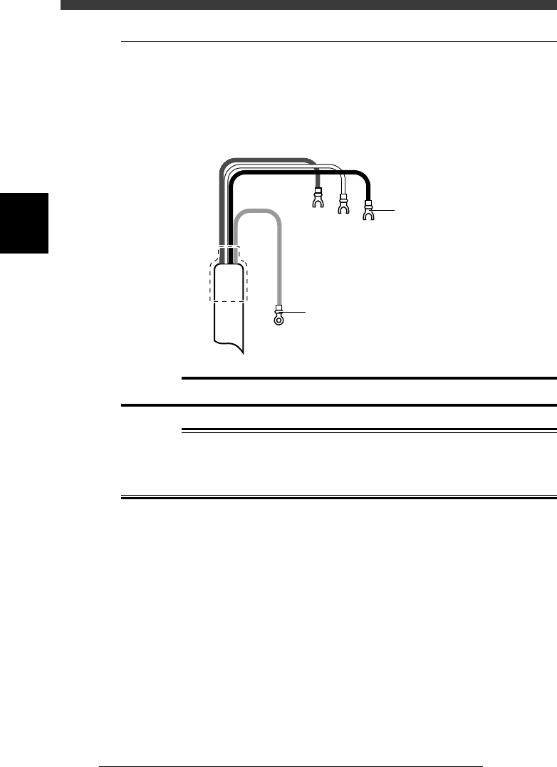
Use a power supply cable shown below, and connect each wire of the cable
to the primary side terminals L1, L2 and L3 of the main breaker QF11
which is located on the lower left of the machine as you face the rear of the
machine, and also to the ground terminal on the frame.
Power supply cable example (4-conductor cabtyre cable)
43801-C0-00
L1
L2
L3
Ground
Green
L=350mm
L=350mm
Round crimp terminal 3.5-4
Y crimp terminal with
insulation tube
TMEV3.5-Y5
c
CAUTION
Use a power supply cable with a conductor wire cross section of at least 3.5mm
2
.
w
WARNING
ENSURE THAT THE POWER SUPPLY IS OFF BEFORE CONNECTING THE
POWER SUPPLY CABLE, TO AVOID THE RISK OF ELECTRICAL SHOCK.
ALSO MAKE CERTAIN THAT THE GROUND CABLE IS PROPERLY
CONNECTED TO THE MACHINE.
8
-5
SED8013110
Service Manual
Chapter 8
8
Power and machine connections
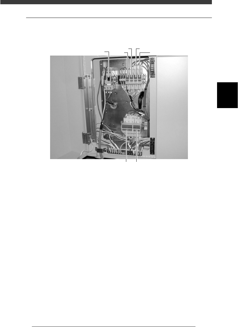
1.3 Breaker
The circuit breaker and protectors are located as shown below.
Breakers
43804-C0-00
QF11
QF22
QF31 QF32
QF21
QF23
QF24
QF11: Main breaker
QF21: Front CRT power supply circuit protector
QF22: Auxiliary AC outlet
QF23: Rear CRT power supply circuit protector
QF24: Controller, I/O and EMG circuit protector
QF31: Power supply circuit protector for all motors
QF32: Conveyor motor power supply circuit protector
8
-6
Service Manual
Chapter 8
SED8013110
8
Power and machine connections
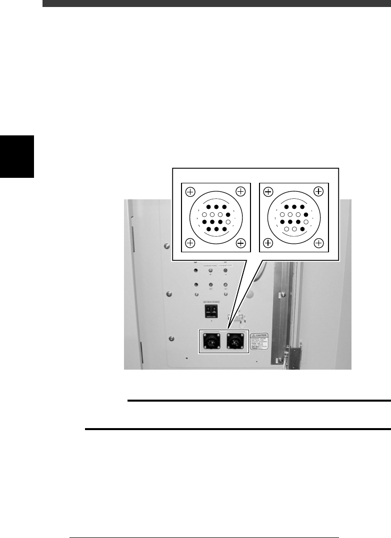
2. Connections to other machines
The mounter ejects the finished PCB when it receives a signal from the
machine in the next process, and then sends a signal to the machine in the
preceding process to request another PCB.
The “NEXT INTERFACE” connector connects to the machine in the next
process, and the “PREVIOUS INTERFACE” connector connects to the
machine in the preceding process. Both connectors are located inside the
lower right panel on the front of the mounter.
Connector type: AMP 206043-1 (14-pin receptacle)
Gate signal connectors
43805-C0-00
PREVIOUS INTERFACE
NEXT INTERFACE
14
11
12
7
4
8
3
1
14
11
12
7
4
8
3
1
c
CAUTION
When the machine in the previous process is an earlier VIOS model (YV100II, etc.), a
separate cable will be required. (See the machine specifications for more details.)