YV180X_Mainte_E.pdf - 第176页
8 -10 Service Manual Chapter 8 SED8013110 8 Power and machine connections PCB transfer signal specifications 45803-C0-00 1 2 3 4 5 6 7 8 9 10 11 12 13 14 BUSY IN (+24V) BUSY IN (N1113) BA OUT (T1832) BA OUT (T1832) NC NC…
8
-9
SED8013110
Service Manual
Chapter 8
8
Power and machine connections
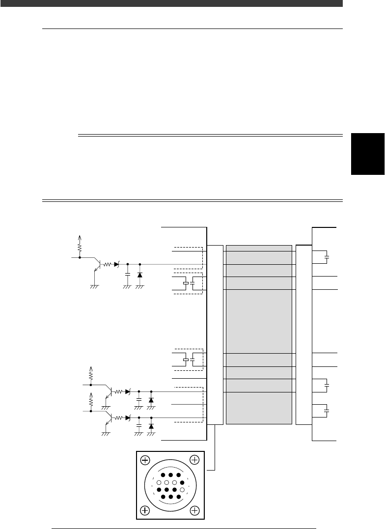
2.2 NEXT INTERFACE circuit
When the following three conditions are met, the NEXT INTERFACE
circuit in the mounter allows the PCB to be carried out.
1. Machine is ready for carrying out the PCB (BA OUT: ON)
2. PCB carry-in signal is input from the downstream machine.
(BUSY IN [N1113]: ON)
3. Automatic operation signal is input from the downstream machine.
(LR IN [N1116]: ON)
n
NOTE
• When the automatic operation signal (LR IN) from the downstream machine turns off
during
transfer of a PCB, the machine temporarily stops carrying out the PC.
• When the PCB being carried out is detected by the exit sensor, the BA OUT signal
turns off.
• Carrying out the PCB is finished when both the BUSY IN and BA OUT turn off.
NEXT INTERFACE circuit
43803-C0-00
1
2
3
4
5
6
7
8
9
10
11
12
13
14
5V
10.5kΩ
0.1µ
IN
(N1120)
This machine
+24V
5V
10.5kΩ
0.1µ
BUSY IN
(N1113)
Downstream
machine
BA OUT
(T1832)
GND
UR OUT
(T1833)
GND
+24V
CONNECTION
BOARD
I/O BOARD
CONNECTION
BOARD
I/O BOARD
1
2
3
4
5
6
7
8
9
10
11
12
13
14
Cable
NEXT INTERFACE
connector
14
11
12
7
4
8
3
1
+24V
5V
10.5kΩ
0.1µ
COUNT RESET
(N1116)
8
-10
Service Manual
Chapter 8
SED8013110
8
Power and machine connections
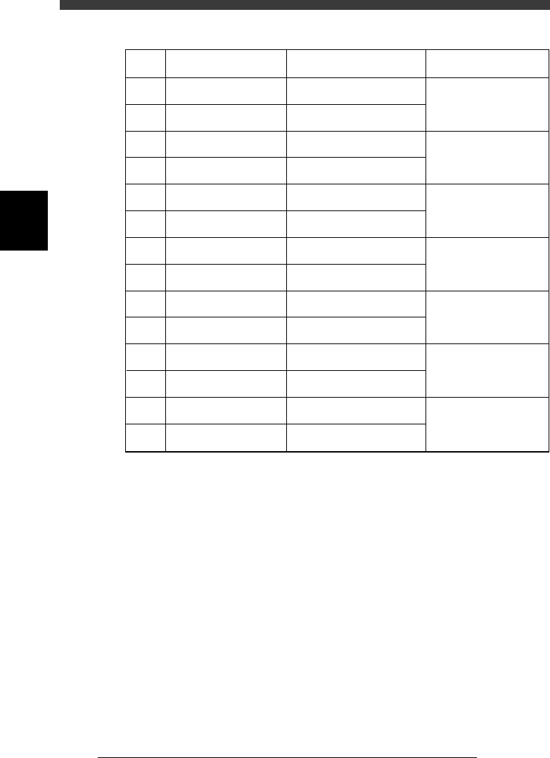
PCB transfer signal specifications
45803-C0-00
1
2
3
4
5
6
7
8
9
10
11
12
13
14
BUSY IN (+24V)
BUSY IN (N1113)
BA OUT (T1832)
BA OUT (T1832)
NC
NC
NC
NC
UR OUT (T1833)
UR OUT (T1833)
LR IN (+24V)
LR IN (N1116)
COUNT RESET (+24V)
COUNT RESET (+24V)
Pin No.
Signal name
I/O specifications Signal specifications
+24V
Tr input
Relay contact (zero voltage)
output
Relay contact (zero voltage)
output
Relay contact (zero voltage)
output
Relay contact (zero voltage)
output
+24V
Tr input
+24V
Tr input
Signal input during PCB
carry-in
Signal output to request
PCB carry-out
Signal output during
automatic operation
Signal input during
automatic operation
Signal input for COUNT
RESET

s-1SED8013110
Index
Index
Symbols
[Ctrl] + [ENTER] keys 1-8
[F1] key 2-3, 2-6
[F10] key 4-71
[F9] key 4-71
A
Adjust Assistant
For mark recognition 4-46
For reference marker 4-66
Adjust target menu 4-10
Adjustment tools
For moving camera 4-37
For multi-vision camera 4-50
Air pressure regulator 6-16
Air supply unit 6-16
Air valve for conveyor unit 6-4
AveGrayLevel 4-43
Axis configuration 4-13
B
Breaker 8-5
Brightness level
Moving camera 4-41
Multi-vision camera 4-55
C
Camera, Machine data edit mode 3-10
Camera scale
Moving camera 4-45
Multi-vision camera 4-58
Caution 3
Change nozzle 4-7, 5-7
Change speed 4-8
Conv. Correct, Position parameter 4-32
Conveyor belt tension 6-9
Conveyor speed 6-6
Conveyor unit adjustment 6-3
Conveyor units command 5-7
Coordinate/spec, Machine data edit mode
3-10
D
Daily inspection 1-4
Discard point, Position parameter 4-21
Down offset, Machine data edit mode 3-7
Dual-direction recognition offset 4-62
Dump box 4-21
Dump component command 4-7
Dump station 4-28
Dump stn.point, Position parameter 4-27
E
Edge clamp, Position parameters 4-18
Error
Conveyor 7-10
Feeder 7-11
FNC nozzle 7-12
Mounting error 7-5
Others 7-13
Pickup error 7-3
Recognition error 7-7
Exit from manual 5-10
F
Feeder out monitor 5-6
Feeder plate information 1-14
Feeder plate offset; Machine data edit mode
3-13
Feeder spec information 1-17
File configuration 1-11
FINE mode; Position parameter 4-15
Flying nozzle information 1-13
FOV & focus
Moving camera 4-38
Multi-vision camera 4-51
G
Grease 1-10
H
Head down valve 4-8
Head spec information 1-13
Head; Machine data edit mode 3-4