YV180X_Mainte_E.pdf - 第115页
4 -57 SED8013110 Service Manual Chapter 4 4 Machine adjust mode 9 Cancel emergency stop and press the [ENTER] key . The head assembly moves and passes repeatedly over the multi-vision camera and the side brightness level…
4
-56
Service Manual
Chapter 4
SED8013110
4
Machine adjust mode
e
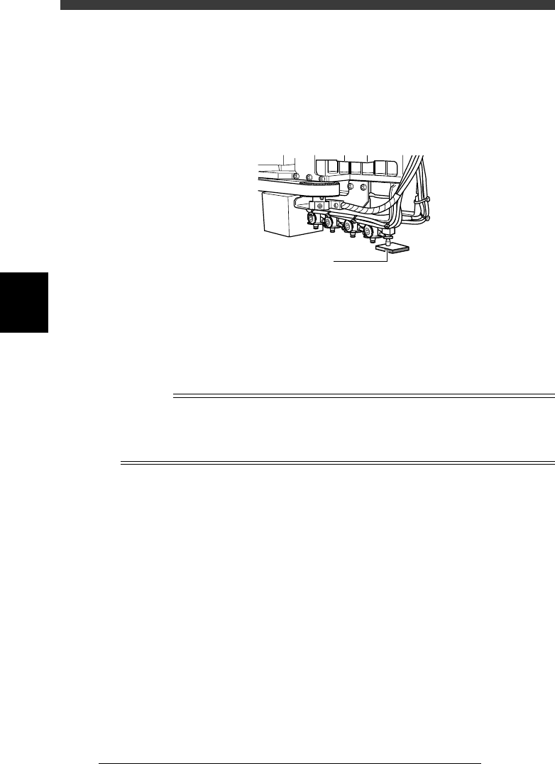
3 Press the emergency stop button, then attach the light
adjuster plate (KM1-M8806-0XX) to Head 1.
Attach the light adjuster plate to Head 1, with the two-tone surface facing
down. The light gray area should be displayed in the entire square window
on the vision monitor.
Attaching the light adjuster plate
43413-C0-00
Light adjuster plate
4 Cancel emergency stop.
Check safety, then release the emergency stop button by turning it
clockwise and press the [READY] button.
5 Check safety, then press the [ENTER] key again.
The head assembly moves and passes repeatedly over the multi-vision
camera and the main brightness level is automatically measured and
optimized. The lighting unit of the selected camera flashes at this time.
Reference
When the lighting level is successfully optimized, the measurement automatically stops. If
the measurement still continues even after the head assembly has passed repeatedly more
than 30 times over the camera, then repeat this adjustment from the beginning. If it fails
again, the lighting unit may be defective, so please contact us. (Same for Steps 7 and 9.)
e
6 Press the emergency button, then invert the light adjuster
plate.
Turn the light adjuster plate upside down and then reattach it to Head 1,
with the white surface facing down.
7 Cancel emergency stop and press the [ENTER] key.
The head assembly moves and passes repeatedly over the multi-vision
camera and the coaxial brightness level is automatically measured and
optimized.
At this point, the lighting unit of the selected camera flashes.
8 Change the light adjuster tool.
After pressing the emergency stop button, remove the light adjuster tool 1
from Head 1 and attach the light adjuster tool 2 (KV7-M8806-0XX) to
Head 1, with the mirror side facing up.
If the camera is not equipped with the side lighting unit, skip Steps 8 and
9.
4
-57
SED8013110
Service Manual
Chapter 4
4
Machine adjust mode
9 Cancel emergency stop and press the [ENTER] key.
The head assembly moves and passes repeatedly over the multi-vision
camera and the side brightness level is automatically measured and
optimized.
The lighting unit of the selected camera flashes at this time.
0 Quit the adjustment.
Follow the messages displayed on the operation monitor to quit the
adjustment and remove the focus adjuster plate. There is no machine data
to be saved in this adjustment.
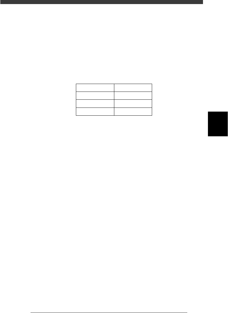
Typical range of multi-vision camera lighting levels
45408-D8-00
Lighting method
Main
Coaxial
Side
Reference Value
128±1
40±1
90±1
4
-58
Service Manual
Chapter 4
SED8013110
4
Machine adjust mode
3.5.3 Calibrating the multi-vision camera scale
The multi-vision camera scale represents an actual measurement (in
microns) equivalent to one pixel. This scale must be calibrated correctly
for accurate recognition of components.
To calibrate the camera scale, you will need an SOP or QFP of known size.
When you run the adjustment utility described below, the camera scale is
automatically calibrated and the XY positions and installation angle R of
the camera are also adjusted at the same time.
1 Prepare a component to be used as a reference.
Use a relatively large, popular SOP or QFP of known size which is
registered in the component database. If using tape feeder components, set
the tape feeder on the feeder plate in advance.
Reference
YAMAHA uses a glass QFP with minimal warp and distortion, specially designed for
adjustment work. To make more accurate adjustments, we recommend using this glass
QFP (sold separately).
2 Edit “Search Area mm” in the component data.
Data registered in the database as a number larger than No.500 cannot be
edited due to write-protection. Make a copy of the data using a number
smaller than No.500, then edit this data. For instance, the following steps
are explained for cases where SOP data is copied onto registration No. 2.
If using a glass QFP (database No. 996), skip this step.
1. Open component database and line up the cursor with component No.
2.
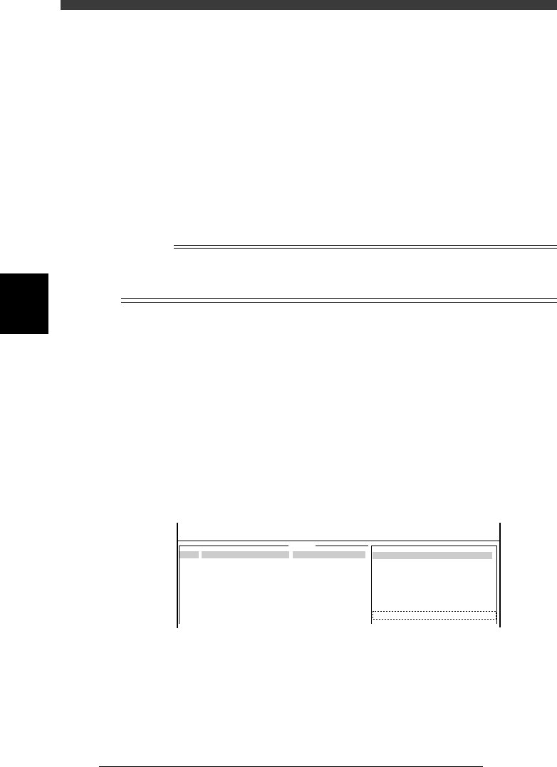
2. Press the [TAB] and [F4] keys to switch the sub-window to “VISION
INFO.” and change the Search Area value to “9.99” (maximum setting).
Since the camera scale is measured while moving the component
slightly, this change compensates for that movement.
47447-C0-00
9.99
COMPONENT NAME
Sample_SOP16-P1.27
COMMENT
example_data
OBJ :
5.VISION INFO.
Search Area
No.
1
2
3
4
5
6
7
<<<APPLICATION>>> 2/DATA/M
<<MODE>> 3/DATABASE
: