YV180X_Mainte_E.pdf - 第173页
8 -7 SED8013110 Service Manual Chapter 8 8 Power and machine connections 2.1 PREVIOUS INTERF ACE circuit When the following three conditions are met, the PREVIOUS INTERF A CE circuit in the mounter allo ws the next PCB t…
8
-6
Service Manual
Chapter 8
SED8013110
8
Power and machine connections
2. Connections to other machines
The mounter ejects the finished PCB when it receives a signal from the
machine in the next process, and then sends a signal to the machine in the
preceding process to request another PCB.
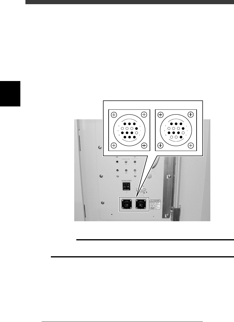
The “NEXT INTERFACE” connector connects to the machine in the next
process, and the “PREVIOUS INTERFACE” connector connects to the
machine in the preceding process. Both connectors are located inside the
lower right panel on the front of the mounter.
Connector type: AMP 206043-1 (14-pin receptacle)
Gate signal connectors
43805-C0-00
PREVIOUS INTERFACE
NEXT INTERFACE
14
11
12
7
4
8
3
1
14
11
12
7
4
8
3
1
c
CAUTION
When the machine in the previous process is an earlier VIOS model (YV100II, etc.), a
separate cable will be required. (See the machine specifications for more details.)
8
-7
SED8013110
Service Manual
Chapter 8
8
Power and machine connections
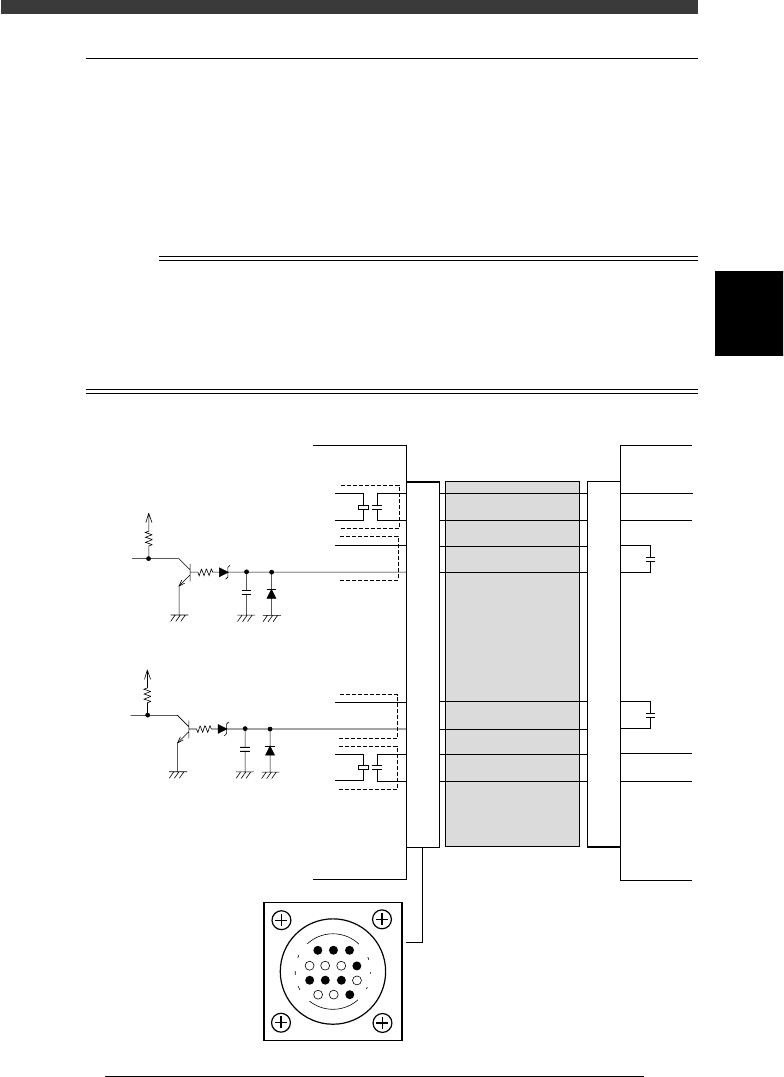
2.1 PREVIOUS INTERFACE circuit
When the following three conditions are met, the PREVIOUS
INTERFACE circuit in the mounter allows the next PCB to be carried in.
1. Machine is ready for carrying in a PCB (BUSY OUT: ON)
2. PCB carry-in signal is input from the upstream machine.
(BA IN [N1115]: ON)
3. Automatic operation signal is input from the upstream machine.
(UR IN [N1117]: ON)
n
Note
• When the automatic operation signal (UR IN) from the upstream machine turns off
during
transfer of a PCB, the machine temporarily stops carrying in the PCB.
• When the PCB being carried in is detected by the entrance sensor, the BUSY OUT signal
turns off.
• Carrying in the PCB is finished when both the BUSY OUT and BA IN turn off.
PREVIOUS INTERFACE circuit
43802-C0-00
1
2
3
4
5
6
7
8
9
10
11
12
13
14
5V
10.5kΩ
0.1µ
N1115
+24V
5V
10.5kΩ
0.1µ
N1117
Upstream
machine
LR OUT
(T1837)
GND
BUSY OUT
(T1831)
GND
+24V
CONNECTION
BOARD
I/O BOARD
CONNECTION
BOARD
I/O BOARD
1
2
3
4
5
6
7
8
9
10
11
12
13
14
Cable
14
11
12
7
4
8
3
1
PREVIOUS INTERFACE
connector
This machine
8
-8
Service Manual
Chapter 8
SED8013110
8
Power and machine connections
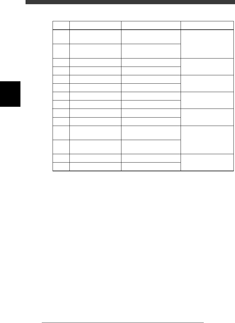
PCB transfer signal specifications
45802-C0-00
1
2
3
4
5
6
7
8
9
10
11
12
13
14
BUSY OUT (T1832)
BUSY OUT (T1831)
BA IN (+24V)
BA IN (N1115)
NC
NC
NC
NC
UR IN (+24V)
UR IN (N1117)
LR OUT (T1837)
LR OUT (T1837)
NC
NC
Pin No.
Signal name
I/O specifications Signal specifications
Relay contact (zero voltage)
output
Relay contact (zero voltage)
output
+24V
Tr input
+24V
Tr input
Relay contact (zero voltage)
output
Relay contact (zero voltage)
output
Signal output during PCB
carry-in
Signal input of PCB
carry-out request
Signal input during
automatic operation
Signal output during
automatic operation