YV180X_Mainte_E.pdf - 第33页
2 -14 Service Manual Chapter 2 SED8013110 2 Machine configuration mode 2.8 Feeder plate information <3/1/B2> When <3/1/B2 FEEDER PLA TE INF .> is selected. the feeder plate infor- mation screen appears showin…
2
-13
SED8013110
Service Manual
Chapter 2
2
Machine configuration mode
2.6 Flying nozzle information
<3/1/A8>
When <3/1/A8 FLYING NOZZLE INF.> is selected, the flying nozzle
information appears showing which head uses which types of flying
nozzles.
Flying nozzle spec information
47208-C0-00
HEAD
1
2
3
4
5
6
7
8
FNC
NotUse
Use
NotUse
Use
NotUse
Use
NotUse
Use
NOZZLE1
NotUse
TYPE-71
NotUse
TYPE-71
NotUse
TYPE-71
NotUse
TYPE-71
NOZZLE2
NotUse
TYPE-72
NotUse
TYPE-72
NotUse
TYPE-72
NotUse
TYPE-72
NOZZLE3
NotUse
TYPE-73
NotUse
TYPE-73
NotUse
TYPE-73
NotUse
TYPE-73
NOZZLE4
NotUse
NotUse
NotUse
NotUse
NotUse
NotUse
NotUse
NotUse
NOZZLE5
NotUse
NotUse
NotUse
NotUse
NotUse
NotUse
NotUse
NotUse
NOZZLE6
NotUse
NotUse
NotUse
NotUse
NotUse
NotUse
NotUse
NotUse
Dia.
0
100
0
100
0
100
0
100
<<<APPLICATION>>> 3/MAINTE/M
<<MODE>> 1/MCH_CONFIG
FNC Specify whether to use flying nozzles. Heads 2, 4, 6,
and 8 should be set to “Use” and Heads 1, 3, 5 and
7 “NotUse”.
Nozzle 1 - 6 Specify the nozzle types to be used.
Dia. Shows the outside diameter of the nozzle unit (in
tenths of a millimeter).
2.7 Head spec information
<3/1/B1>
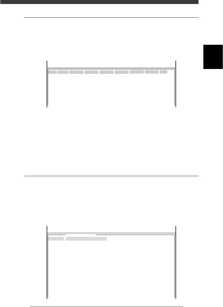
When <3/1/B1 HEAD SPEC INF.> is selected, the head spec information
screen appears showing which types of nozzles can be attached to each
head. Digit “0” means the nozzle is attachable and code “-” means not
attachable.
Head spec information
47209-C0-00
<<<APPLICATION>>> 3/MAINTE/M
<<MODE>> 1/MCH_CONFIG
TYPE- 71
Head
A01
A02
A03
A04
A05
A06
A07
A08
B01
B02
B03
B04
B05
B06
B07
B08
Nozzle 1 2
0000--------------------
000---------------------
0000--------------------
000---------------------
0000--------------------
000---------------------
0000-0------------------
000---------------------
0000--------------------
000---------------------
0000--------------------
000---------------------
0000--------------------
000---------------------
0000-0------------------
000---------------------
2
-14
Service Manual
Chapter 2
SED8013110
2
Machine configuration mode
2.8 Feeder plate information
<3/1/B2>
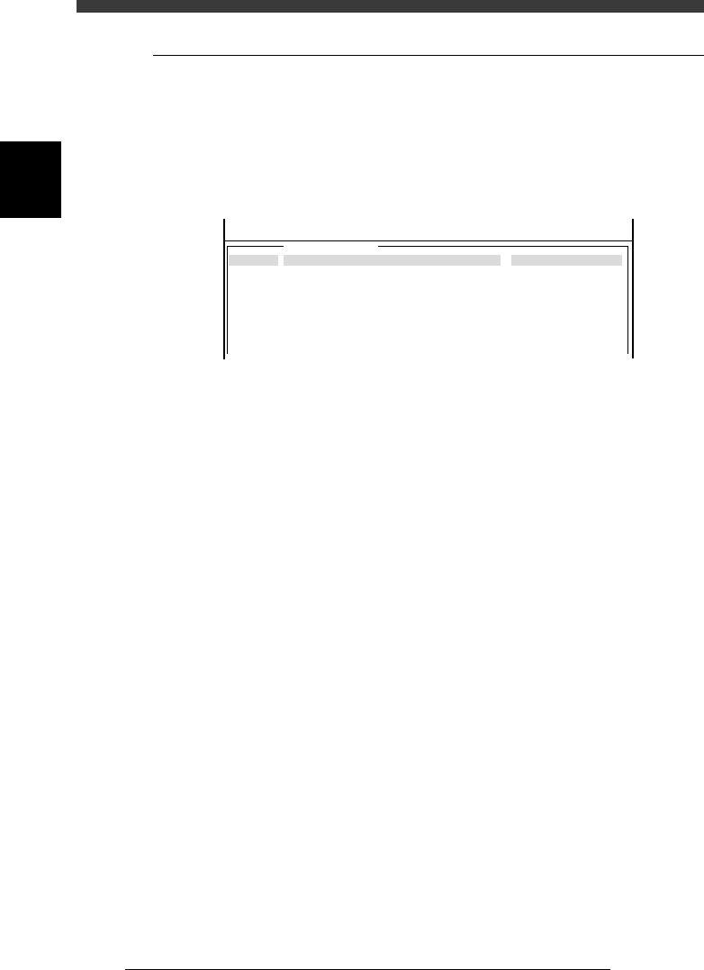
When <3/1/B2 FEEDER PLATE INF.> is selected. the feeder plate infor-
mation screen appears showing the feeder types that can be installed in
each feeder set position. Digit “0” means the feeder can be installed and
code “-” means it cannot be installed.
Feeder plate information
47210-C0-00
Set No.
001
002
003
004
005
006
007
008
Type
<<<APPLICATION>>> 3/MAINTE/M
<<MODE>> 1/MCH_CONFIG
00----------0------------------0000000000
000000------0------------------0000000000
000000000-0-0------------------0000000000
0000000000000------------------0000000000
0000000000000------------------0000000000
0000000000000------------------0000000000
0000000000000------------------0000000000
0000000000000------------------0000000000
User
1
2
3
4
5
6
7
8
Tbl
0
0
0
0
0
0
0
0
Plt
0
0
0
0
0
0
0
0
Pos
0
0
0
0
0
0
0
0
Base
0
0
0
0
0
0
0
0
Idx
0
1
2
3
4
5
6
7
1234
8mmTape
2
-15
SED8013110
Service Manual
Chapter 2
2
Machine configuration mode
2.9 Nozzle spec information
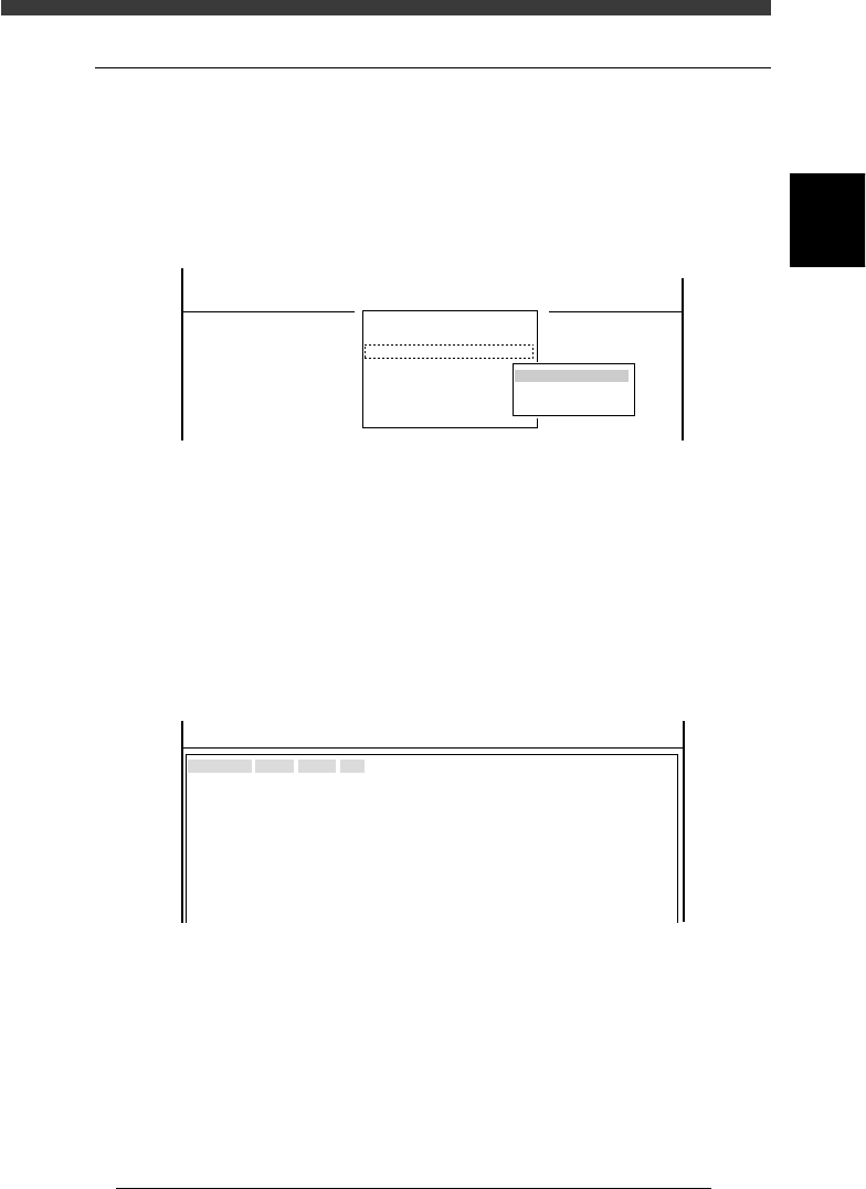
<3/1/B3>
When <3/1/B3 NOZZLE SPEC INF.> is selected, the submenu box
appears for selecting “NOZZLE SPEC CMN. (nozzle spec common)
information” and “NOZZLE SPEC TYP. (nozzle spec type) information”.
Each item on this submenu is explained below.
Nozzle spec information submenu
47211-C0-00
B1 HEAD SPEC. INF.
B2 FEEDER PLATE SPEC INF.
B3 NOZZLE SPEC INF.
B4 FEEDER SPEC INF.
B5
B6 DISPENSE SEQ. INF.
B7 DISPENSE COR. INF.
B0 EXIT
NOZZLE SPEC
NOZZLE SPEC CMN.
NOZZLE SPEC TYP.
<<<APPLICATION>>> 3/MAINTE/M
<<MODE>> 1/MCH_CONFIG
<COMMAND_LIST> B/SPEC_INF
2.9.1 Nozzle spec common information
The nozzle spec common information shows specifications of nozzles used
with this machine.
Nozzle spec common information
47212-C0-00
Nozzle
TYPE- 71
TYPE- 72
TYPE- 73
TYPE- 74
TYPE- 75
TYPE- 76
TYPE- 77
TYPE- 78
TYPE- 79
TYPE- 7A
TYPE- 7B
<<<APPLICATION>>> 3/MAINTE/M
<<MODE>> 1/MCH_CONFIG
H. mm
0.00
0.00
0.00
-1.00
0.00
0.00
0.00
0.00
0.00
0.00
0.00
Num
100
100
100
100
100
100
100
100
100
100
100
Dia
13
20
30
80
0
30
0
0
0
0
0
H mm Difference in nozzle length in relation to reference
nozzle
Num The number of nozzles used with this machine
Dia. Nozzle tip diameter (in tenths of a millimeter)