YV180X_Mainte_E.pdf - 第45页
3 -8 Service Manual Chapter 3 3 Machine data edit mode SED8013110 2.4 Nozzle correction Selecting “ NozzleCorrection ” from the “ Head ” submenu opens the Nozzle Correction screen as shown belo w . Data entered here are …
3
-7
Service Manual
3
Machine data edit mode
Chapter 3
SED8013110
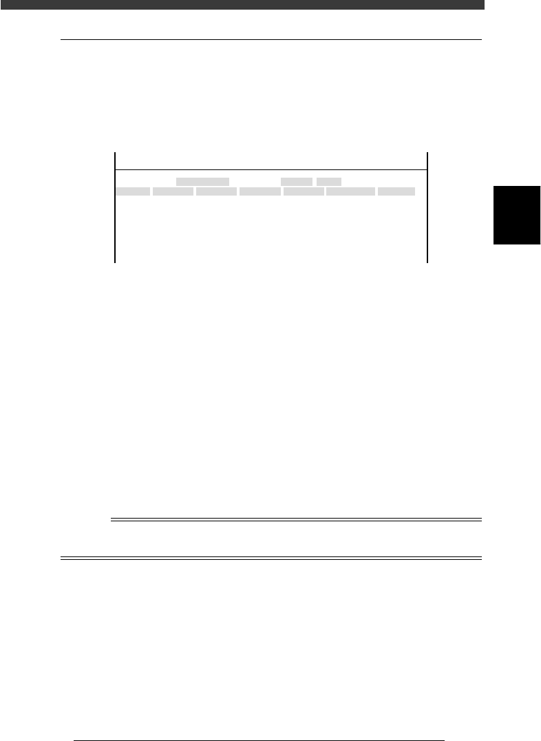
2.3 Down offset
Selecting “Down Offset” from the “Head” submenu opens the Head Down
Offset screen as shown below. Data entered here are offset settings for
correcting a positional shift of the rotational center of each head which
occurs when it descends to pick up a component, lighting method, etc.
Head Down Offset screen
47305-D8-00
<<<APPLICATION>>> 3/MAINTE/M
<<MODE>> 2/MCH_DATA
Head No.
Head 1 A
Head 2 A
Head 3 A
Head 4 A
Head 5 A
Head 6 A
Head 7 A
Head 8 A
OBJECT
Vacuum Level
TCH.UNIT SPEED
- - - - - - - -
Y
0.000
0.000
0.000
0.000
0.000
0.000
0.000
0.000
X
0.000
0.000
0.000
0.000
0.000
0.000
0.000
0.000
X correct
0.000
0.000
0.000
0.000
0.000
0.000
0.000
0.000
Y correct
0.000
0.000
0.000
0.000
0.000
0.000
0.000
0.000
HeadType
Fore
Fore
Fore
Fore
Fore
Fore
Fore
Fore
FIneMode
impossible
impossible
impossible
impossible
impossible
impossible
impossible
impossible
X, Y Shows XY offset (mm) of the rotational center of
each head when it descends to pick up a compo-
nent. This parameter affects the component pickup
action only, and does not affect the mounting
accuracy.
X, Y correct Shows XY offset to correct a mounting position shift
caused by a component which is not perpendicular
to the PCB surface when picked up by a nozzle. Set
this parameter to “0.000” in most cases.
HeadType Shows the lighting method that matches each head.
All heads of the YV180X should be set to “Fore”.
FineMode This function cannot be used with the YV180X and
should be set to “impossible”.
n
NOTE
Head down offset can be automatically adjusted by running the AMF (auto mount
feedback) utility. See the separate AMF manual for details.
3
-8
Service Manual
Chapter 3
3
Machine data edit mode
SED8013110
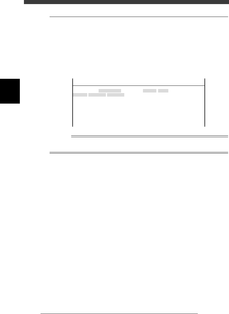
2.4 Nozzle correction
Selecting “NozzleCorrection” from the “Head” submenu opens the Nozzle
Correction screen as shown below. Data entered here are offset settings
(mm) for correcting a positional shift of the center of each head. These
positional shifts for example occur if the nozzle shaft is bent an amount
equal to the difference between recognition height and mounting height
even though nozzle angle remains the same.
Nozzle Correction screen
47306-D8-00
<<<APPLICATION>>> 3/MAINTE/M
<<MODE>> 2/MCH_DATA
Head No.
Head 1 A
Head 2 A
Head 3 A
Head 4 A
Head 5 A
Head 6 A
Head 7 A
Head 8 A
OBJECT
NozzleCorrection
TCH.UNIT SPEED
- - - - - - - -
Y
0.000
0.000
0.000
0.000
0.000
0.000
0.000
0.000
X
0.000
0.000
0.000
0.000
0.000
0.000
0.000
0.000
n
NOTE
Nozzle correction can be automatically adjusted by running the AMF (auto mount
feedback) utility. See the separate AMF manual for details.
3
-9
Service Manual
3
Machine data edit mode
Chapter 3
SED8013110
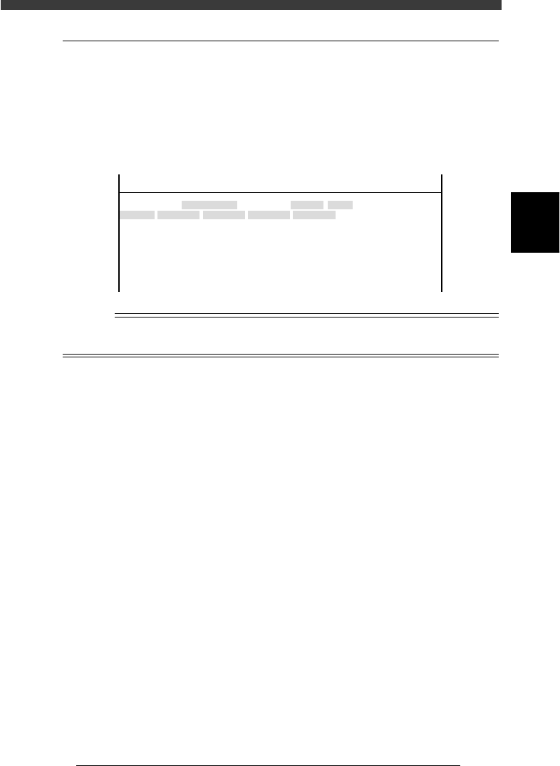
2.5 R axis accuracy
Selecting “R Axis Accuracy” from the “Head” submenu opens the R Axis
Accuracy screen as shown below. Data entered here are offset settings
(deg.) for correcting the mounting angles of each head at 0, 180, 90 and -90
deg. Since this parameter at is used as a reference at 0 degrees, it is always
set to “0.000”.
R Axis Accuracy screen
47307-C0-00
<<<APPLICATION>>> 3/MAINTE/M
<<MODE>> 2/MCH_DATA
Head No.
Head 1 A
Head 2 A
Head 3 A
Head 4 A
Head 5 A
Head 6 A
Head 7 A
Head 8 A
OBJECT
R Axis Accuracy
TCH.UNIT SPEED
- - - - - - - -
0°
0.000
0.000
0.000
0.000
0.000
0.000
0.000
0.000
180°
0.000
0.000
0.000
0.000
0.000
0.000
0.000
0.000
90°
0.000
0.000
0.000
0.000
0.000
0.000
0.000
0.000
-90°
0.000
0.000
0.000
0.000
0.000
0.000
0.000
0.000
n
NOTE
R axis accuracy can be automatically adjusted by running the R Axis Accuracy command
in MCH_ADUST mode.