YV180X_Mainte_E.pdf - 第47页
3 -10 Service Manual Chapter 3 3 Machine data edit mode 3. Camera W hen “ Camer a ” is selected from the <3/2/MCH_D A T A> main men u, the submen u a ppear s as sho wn belo w . Each item on this submenu is explaine…
3
-9
Service Manual
3
Machine data edit mode
Chapter 3
SED8013110
2.5 R axis accuracy
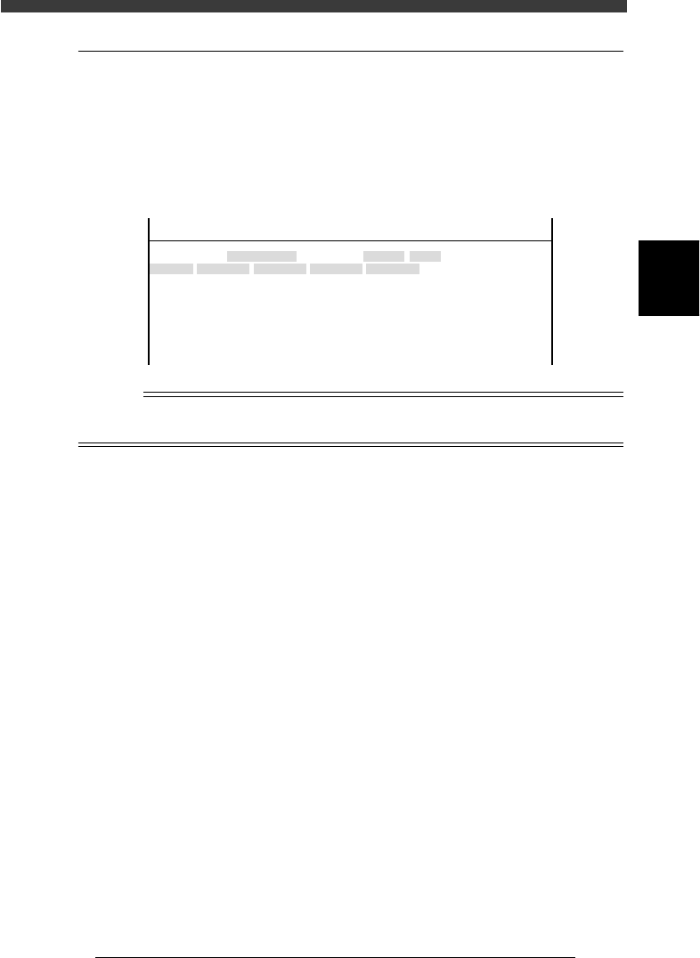
Selecting “R Axis Accuracy” from the “Head” submenu opens the R Axis
Accuracy screen as shown below. Data entered here are offset settings
(deg.) for correcting the mounting angles of each head at 0, 180, 90 and -90
deg. Since this parameter at is used as a reference at 0 degrees, it is always
set to “0.000”.
R Axis Accuracy screen
47307-C0-00
<<<APPLICATION>>> 3/MAINTE/M
<<MODE>> 2/MCH_DATA
Head No.
Head 1 A
Head 2 A
Head 3 A
Head 4 A
Head 5 A
Head 6 A
Head 7 A
Head 8 A
OBJECT
R Axis Accuracy
TCH.UNIT SPEED
- - - - - - - -
0°
0.000
0.000
0.000
0.000
0.000
0.000
0.000
0.000
180°
0.000
0.000
0.000
0.000
0.000
0.000
0.000
0.000
90°
0.000
0.000
0.000
0.000
0.000
0.000
0.000
0.000
-90°
0.000
0.000
0.000
0.000
0.000
0.000
0.000
0.000
n
NOTE
R axis accuracy can be automatically adjusted by running the R Axis Accuracy command
in MCH_ADUST mode.
3
-10
Service Manual
Chapter 3
3
Machine data edit mode
3. Camera
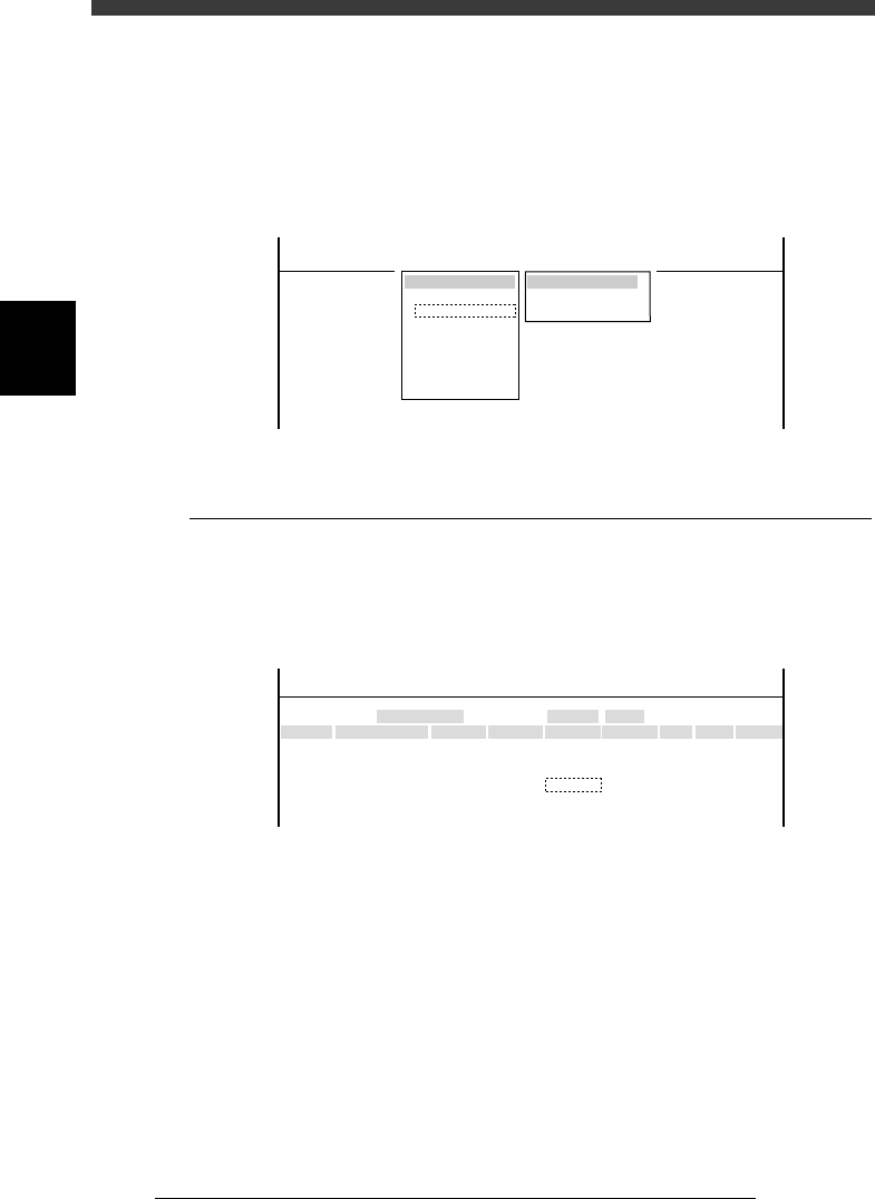
When “Camera” is selected from the <3/2/MCH_DATA> main menu, the
submenu appears as shown below. Each item on this submenu is explained
in the following sections.
Submenu box when “Camera” is selected
47308-C0-00
SUB MENU
Coordinate/Spec
Vision Parameter
MCHDATA SORT
Head
Camera
Machine
Tray Changer
Station
Other
Precision
Spare Data
<<<APPLICATION>>> 3/MAINTE/M
<<MODE>> 2/MCH_DATA
3.1 Coordinate/spec
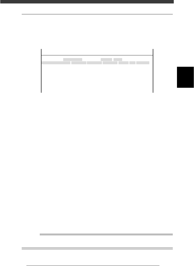
Selecting “Coordinate/Spec” from the “Camera” submenu opens the
Coordinate/Spec screen as shown below. Data entered here are coordinates
and lighting type of each camera used in this machine.
Coordinate/Spec screen
47309-D8-00
<<<APPLICATION>>> 3/MAINTE/M
<<MODE>> 2/MCH_DATA
Cam No.
Cam 1A
Cam 3A
Cam 5A
Cam 2A
Cam 4B
Cam 6B
X
152.042
0.000
382.925
-152.051
0.000
472.334
OBJECT
Coorcinate/Spec
TCH.UNIT SPEED
- - - - - - - -
Y
-0.166
0.000
0.091
0.446
0.000
-0.064
Z
0.000
0.000
17.140
0.000
0.000
17.390
R
-0.305
0.000
-0.386
-0.099
0.000
-0.515
Type
Move
- - - - - - - - - - - - -
Dig.Multi
Move
- - - - - - - - - - - - -
Dig.Multi
Size
0
0
45
0
0
45
Max Z
0
0
7
0
0
7
Light Sp
TypeA
TypeA
TypeG
TypeA
TypeA
TypeG
X, Y Moving camera: XY position (mm) of camera center
from the head reference position
Multi camera: XY position (mm) of camera center
from the machine origin.
Z Height (mm) of bottom of component while being
recognized with the multi camera.
R Camera installation angle (deg.)
Size Maximum component size recognizable in XY
directions
Height Maximum component height (mm) recognizable in
Z direction
Light Sp Lighting type for each camera
3
-11
Service Manual
Chapter 3
SED8013110
3
Machine data edit mode
3.2 Vision parameter
Selecting “Vision Parameter” from the “Camera” submenu opens the
Vision Parameter screen as shown below. Data entered here are vision
parameters used to perform image processing.
Vision Parameter screen
47310-D8-00
<<<APPLICATION>>> 3/MAINTE/M
<<MODE>> 2/MCH_DATA
X
10.465
0.000
48.828
0.000
0.000
0.000
-3.606
10.489
0.000
OBJECT
Vision Parameter
TCH.UNIT SPEED
- - - - - - - -
Y
10.399
0.000
48.809
0.000
0.282
0.000
1.001
10.428
0.000
Speed
1100.000
1100.000
0.000
0.065
1100.000
Div.
12PULS
8PULS
12PULS
Object
Camera 1 Scale
Camera 2 Scale
Camera 3 Scale
Camera 4 Scale
Camrea 2 Delta Scale
Camera 3 Delta Scale
Camera 4 Delta Scale
Camera 2 Delta pos.
Camera 3 Delta pos.
A
A
A
A
A
A
A
A
A
Main
128
Coax.
40
SIde
90
Object Shows camera numbers and parameter. Camera
numbers. used here are identical with those shown
on the Coordinate/Spec screen.
Scale - X, Y XY measurement (in microns) equivalent to one
pixel, used as a camera scale.
Scale - Speed Speed at which the head moves above the camera
during component recognition.
Delta Scale X, Y Camera scale offset for correcting the fact that a
thicker component appears larger than a thinner
component of the same size. (in microns)
Delta pos. - X, Y Positional offset for a deviation of the nozzle center
relative to the camera center, which occurs if the
nozzle’s vertical axis is not perfectly perpendicular
to the camera.
Delta pos. - Speed Offset for a positional shift caused by dual-direction
recognition.
Scale - Div. Division pulse at which the head moves above the
camera during component recognition.
Main Main lighting level for multi camera
Coax. Coaxial lighting level for multi camera
Side Side lighting level for multi camera
n
NOTE
Vision parameters can be automatically adjusted by running the Camera Scale command
in MCH_ADUST mode.