YV180X_Mainte_E.pdf - 第121页
4 -63 SED8013110 Service Manual Chapter 4 4 Machine adjust mode 4 Press the [ENTER] key to advance to the next step. 5 Enter the component database No. and press the [ENTER] key . Here, enter the database No. of the SOP …
4
-62
Service Manual
Chapter 4
SED8013110
4
Machine adjust mode
3.5.4 Adjusting the dual-direction recognition
offset
The multi-vision camera can recognize components traveling from right
and from left. This recognition offset between the dual directions is entered
as the “Dual Rec. Offset” data on the Position screen, and must be adjusted
correctly for accurate mounting. It is recommended that you use an SOP or
QFP such as those used in the camera scale adjustment.
Reference
YAMAHA uses a glass QFP with minimal warp and distortion, specially designed for
adjustment work. To make more accurate adjustments, we recommend using this glass
QFP (sold separately).
e
1 Check that an appropriate nozzle is attached to Head 1.
Press the emergency stop button, then attach a Type 73A or 74A nozzle to
Head 1. (If using a glass QFP, attach a Type 74A nozzle.)
2 Cancel emergency stop.
When the machine is in emergency stop, release the emergency stop
button by turning it clockwise and press the [READY] button.
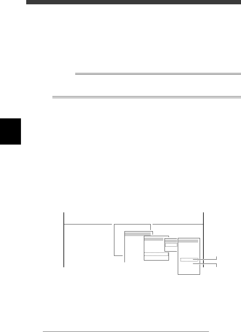
3 Run the “Multi Camera” − “Dual Recognition” command.
1. Select <3/3/B1 ADJUST TARGET> − ”Multi Camera” - “Dual Recogni-
tion” and press the [ENTER] key.
2. Select the conveyor table and the camera No. by pressing the [ENTER]
key.
The A-table multi-vision camera is designated “Cam. 5” and the B-table
multi-vision camera “Cam. 6”.
47445-D8-C0
B1 ADJUST TARGET
Object
Multi Camera
<<<APPLICATION>>> 3/MAINTE/M
<<MODE>> 3/MCH_ADJUST
<COMMAND_LIST> B/SAVE & QUIT
Target
FOV & Focus
Brightness
Camera Scale
Dual Recognition
Marker
table
A table
B table
Target
Cam. 1
Cam. 2
Cam. 3
Cam. 4
Cam. 5
Cam. 6
Cam. 7
Cam. 8
A Table
Multi Camer
a
B Table
Multi Camer
a
4
-63
SED8013110
Service Manual
Chapter 4
4
Machine adjust mode
4 Press the [ENTER] key to advance to the next step.
5 Enter the component database No. and press the [ENTER]
key.
Here, enter the database No. of the SOP you have prepared.
47451-C0-00
Please input the database number which has already
prepared . . .
Database No. 2
A461
6 Check safety, then press the [ENTER] key twice.
The head assembly moves to a point where Head 1 is ready to pick up a
component.
Reference
When you are using a tape feeder, the feeder set No. input box appears, so follow the
message on the screen. (In this case, the component is automatically picked up and Steps 7
to 9 are skipped.
e
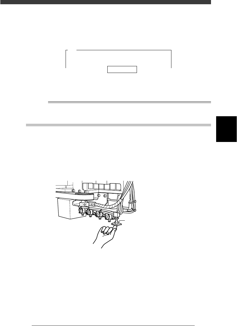
7 Press the emergency stop button then attach the compo-
nent to Head 1 by hand.
When you use a rectangular component, align its long side in parallel with
the X-axis.
Attaching the component to Head 1
43414-D8-00
Attach component to Head 1.
8 When the component has been attached, press the [ENTER]
key.
9 Cancel emergency stop.
Release the emergency stop button by turning it clockwise and press the
[READY] button on the YPU.

4
-64
Service Manual
Chapter 4
SED8013110
4
Machine adjust mode
0 Check safety, then press the [ENTER] key again.
The head assembly moves and passes repeatedly over the multi-vision
camera and the dual-direction recognition offset is measured. The results
are then displayed in the upper right corner of the operation monitor.
47452-D8-00
<<<Adjusting!!>>>
Now it is adjusting the dual direct recognition offset.
The values are measured · · ·
A547
Result
<<<Result>>>
The following data is the result of the adjustment of
the multi camera dual direct recognition offset.
To save the result in memory, · · ·
Camera No.
X Offset
=
=
5
0.750
A546
q Press the [ENTER] key to save the results.
Press the [ESC] key if you want to cancel the results.
w When the measurement is complete, dump the component.
Press the [ENTER] key to dump the component automatically or follow the
message on the operation monitor.
e Save the results.
Select <B2 SAVE DATA> or <B0 SAVE & QUIT> and press the [ENTER]
key. (To quit without saving, select <B3 RECOVER ADJUST> or <B7
QUIT> and press the [ENTER] key.)