YCP10 Users_E.pdf - 第102页
4-6 4 Daily operation e 3 Set the matrix pins (or board support jigs). Press the emergency stop button and open the upper door . Arrange the matrix pins on the push-up plate according to the width of a production boar d.…
4-5
4
Daily operation
4. Changing the conveyor unit setup
When producing boards that are different from the previous production board, you need to change the
conveyor unit setup to match the selected board. (This procedure is not necessary when you are producing
the same board as last time.)
c
CAUTION
When producing board whose width is narrower than the previous production board, remove in advance the matrix
pins (or board support jigs) from the push-up plate.
1
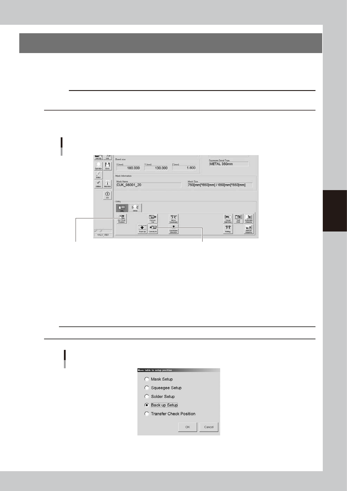
Open the [Unit]-[Conveyor] tab.
The buttons on this screen are used in the following steps to change the conveyor unit setup.
[Unit]-[Conveyor] tab
Step 2:
[SW. Prod. Position] button
Step 5:
[Convey In] button
64406-N1-10
2
Press the [SW. Prod. Position] button.
Select the setup item.
1. When rearranging the backup pins, select “Transfer Check Position”. The conveyor will move to the
setup position and the conveyor width will be automatically adjusted to match the board size.
2. When changing the whole matrix plate, select “Backup Setup”. The conveyor will move to the setup
position and the conveyor will be adjusted to the maximum width, allowing you to remove the matrix
plate.
n
NOTE
When removing the matrix plate, check for safety and then lift it straight up while holding firmly with both hands.
“Move table to setup position” screen
64407-N1-00
4-6
4
Daily operation
e
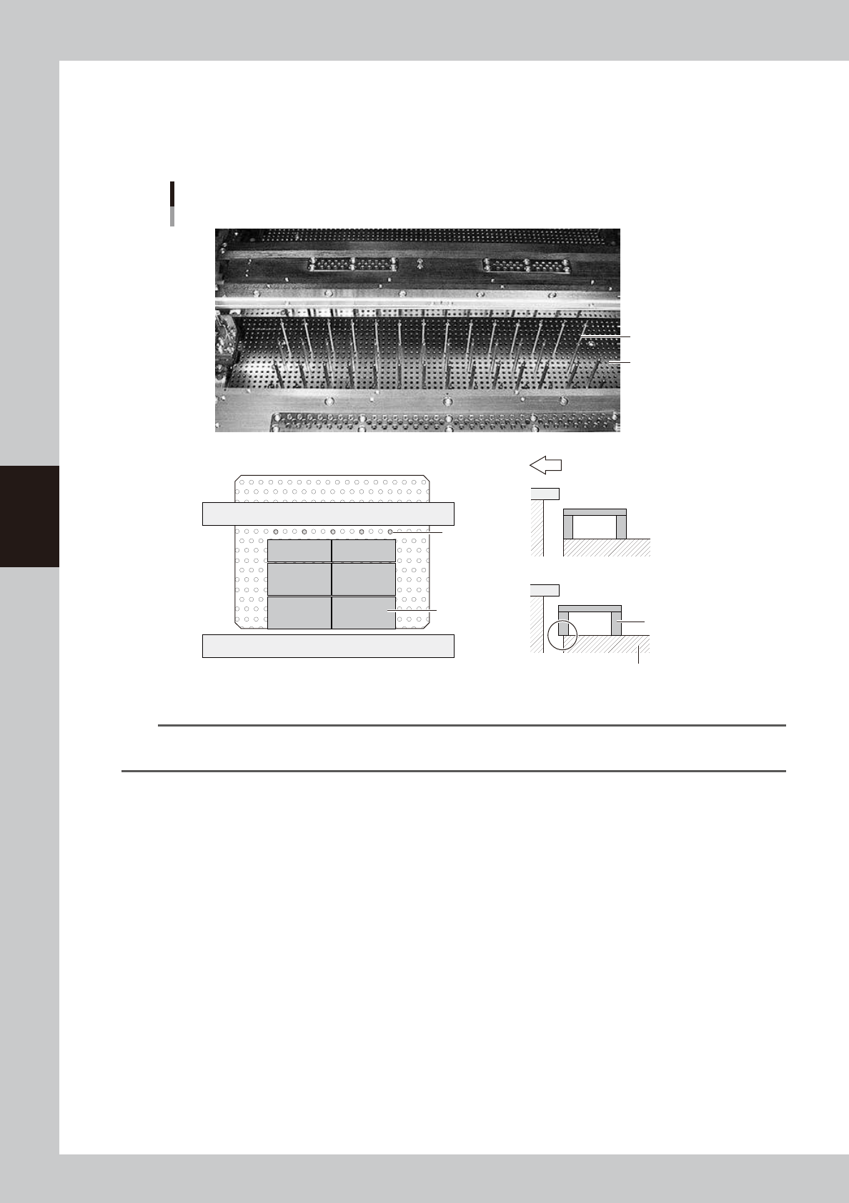
3
Set the matrix pins (or board support jigs).
Press the emergency stop button and open the upper door. Arrange the matrix pins on the push-up
plate according to the width of a production board. When using optional board support jigs, they can
also be used together with the matrix pins.
OK
Not OK
Arranging the matrix pins
Matrix pins
(When board support jigs and matrix pins are used together)
Board support jig
Board support jig
Machine front side
Matrix plate
Matrix pins
Matrix plate
63402-N1-00
n
NOTE
When the matrix pin arrangement has been input by pressing the [Backup Pin Pos.] button on the [Print]-[Board] tab
screen, this is convenient to arrange the matrix pins. (For more details, see "3. Matrix pin arrangement" in Chapter 7.)
4
Cancel emergency stop.
Close the upper door, release the emergency stop button and press the [READY] button on the
operation panel.
5
Press the [Convey In] button to load a board.
Load a board by following the message that appears on the screen, and the board will be
automatically clamped in printing position.
e
6
Check that the board is uniformly clamped on the conveyor.
After pressing the emergency stop button, lightly press and tap on the board by hand to check that
there is no warp or play in the board.
4-7
4
Daily operation
5. Replacing the cleaning gauze roll
If the cleaning gauze roll is wound up completely or if the gauze roll with a different size needs to be used
during the setup work, follow the steps below to replace the cleaning gauze roll.
c
CAUTION
For a new gauze roll, use YAMAHA genuine spare parts listed in the table below to prevent any trouble.
n
Gauze roll part No.
Part No. Part name Notes
KHT-M3660-00X BENCOT,ROLL 530 Roll sheet width, 530 mm
KGY-M3660-A0X BENCOT,ROLL 440 Roll sheet width, 440 mm
KGY-M3660-B0X BENCOT,ROLL 360 Roll sheet width, 360 mm
KGY-M3660-C0X BENCOT,ROLL 260 Roll sheet width, 260 mm
c
CAUTION
Select a gauze roll width that matches the squeegee head size. Using the wrong gauze roll width might damage the
squeegee head and mask.
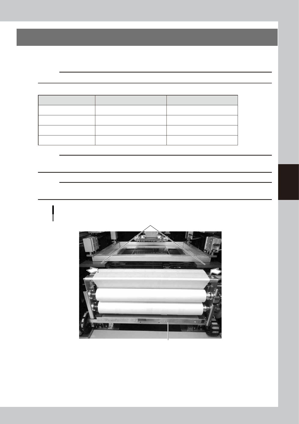
c
CAUTION
When moving the cleaning unit manually, be careful not to catch your hand in the clearance between the cleaning
unit and mask plate (portion indicated by an arrow in the figure below).
Cleaning unit
Mask plate
Cleaning unit
63403-N1-00