YCP10 Users_E.pdf - 第254页
2-7 2 Inspection and maintenance 2.3 Adjusting the conveyor transfer belt tension T he conveyor mo ves by belt dri ve to load boards ready for printing and to unload the finished boards. If the convey or transfer belt (h…
2-6
2
Inspection and maintenance
Section Check item Checkpoint Contents of inspection/work
Weekly (Date) Monthly
/ / / / /
Cleaning Lubrication
Cleaner
Cleaner unit
Up/down
operation
Roll sheet wind-
up
• Check that the up/down operation timing
is correct.
• Check that the roll sheet is wound up
correctly.
Contamination
inside head
Solvent dispense
status
Check the cleaning solvent dispense
status or the head for contamination.
Y-direction guide
• Check for foreign matter or solder
sticking.
* As needed, wipe away excess grease
after the grease has been applied.
Suction unit
hose
Crack,
deterioration
* Check the hose for crack. If the hose
deteriorates, replace it.
• Check that the swing unit beside the
cleaner head functions smoothly.
Suction unit
Filter inside
suction unit
Operation
* Clean the contamination of the filter.
Replace the filter if necessary.
Others
Each sensor
Contamination
on sensor
Operation
* Check the senor or dog for foreign
matter or solder sticking.
Clean the sensor or dog if necessary.
Air supply part
Air filter
Mist filter
* Clean the contamination of the filter.
Replace the filter if necessary.
Controller Filter
* Clean the contamination of the filter.
Replace the filter if necessary.
Cooling fan
(Lower portion
of front/lower
portion of rear/
inside of panel)
Filter
* Clean the contamination of the filter.
Replace the filter if necessary.
2.2 Parts recommended for periodic replacement
For parts listed in the table below, it may be predicted that the service life of the part is expired or the part
deteriorates even though no trouble is found through the visual check during the periodic inspection.
To maintain the performance of the machine at its optimal operating level, it is recommended to periodically
replace these parts.
n
Periodic replacement parts
Part No. Part name Q'ty Location used Replacement interval
KLV-M37D9-00X
TUBE 25
1
ø25-suction hose connected from
the left side of the cleaner unit to
the rear of the machine.
Replace periodically every time
the total production quantity
reaches 3 million boards.
KHU-M3756-01X PUMP 1 Solvent pump
Replace every time the number
of suction unit operation cycles
reaches 1,440 thousand cycles.
Check the operation records on
the [Unit log]-[Cleaner] tab screen.
KLW-M91V1-00X VALVE 1 Valve
Replace every time the operation
count reaches 20 millions.
KHT-M362E-20X FILTER, SUB ASSY 1 Filter for solvent pump
Replace these parts at the same
time the solvent pump is replaced.
c
CAUTION
Parts (Part No.) listed above is current as of the issue date of this manual. When ordering a replacement part, please
check for the latest information.
c
CAUTION
Part Nos. are subject to change without prior notice. When ordering a replacement part, contact your local sales
dealer to check its part No.
2-7
2
Inspection and maintenance
2.3 Adjusting the conveyor transfer belt tension
The conveyor moves by belt drive to load boards ready for printing and to unload the finished boards. If the
conveyor transfer belt (hereafter "belt")is too loose, it may slip on the pulleys causing unstable board transfer. If
the belt is too tight, it may break or wear excessively.
If requiring the tension adjustment after replacing belt or inspected, adjust with the following procedures.
The tension of each belt on the fixed and movable rails should be adjusted evenly.
n
NOTE
The 2 types of belt below are set on the machine depending on the shipping time. The belt path and procedures of
applying tension also vary. Check the belt type to adjust it correctly.
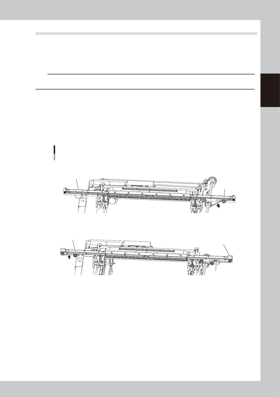
n
Distinguishing between belts
Type A (KLV-M9127-00X)
•
The idler is not set to the downstream side (in front of exit).
•
The tension is adjusted by moving tensioner (pulley).
Type B (KLV-M9127-01X)
•
The idler is set to the downstream side (in front of exit).
•
The tension is adjusted by moving the tension adjustment plate. (Tensioner is not moved directly.)
Distinguishing between belts
Tension
Measurement
position
Tension
measurement
Position
No idler
Type A
Type B
Idler
Tension
adjustment plate
Tensioner
The shape of end block is
different from type A.
53230-N1-00
n
Required tools
•
Hex wrenches (3 mm, 4 mm, 5 mm)
•
Tension meter
•
Permanent marker (marking tension position)
•
Scale (Measuring SPAN)
2-8
2
Inspection and maintenance
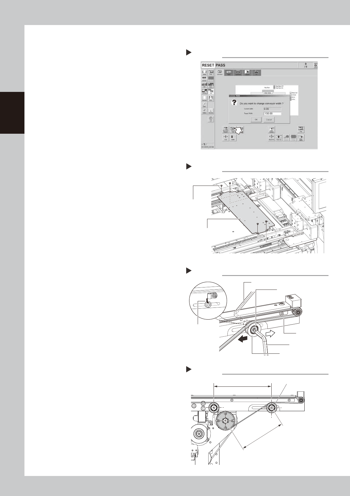
2.3.1 Belt Type A
1
Change the conveyor width to a
convenient width for maintenance
work.
1. Press the [Width] button to display the
"Conveyor Width" screen.
2. In the "Target Width" box, enter a width
wide enough to insert hex wrench and
press [OK] button.
The conveyor is changed to the specified
width.
54203-N1-00
e
2
Press the emergency stop button
and open the upper door.
The machine must be in emergency stop to
ensure safety during work.
3
Remove the mask guide plates.
Remove 4 bolts with hex wrench (3 mm) and
detach mask guide plate. The mask guide
plate is on left and right.
53220-N1-10
4
Loosen the belt tension.
1. Mark the current tensioner position with
permanent marker before loosening belt.
2. Loosen tensioner mounting bolt with hex
wrenches (4 mm and 5 mm).
53221-N1-10
5
Tighten the tensioner temporarily.
If applying tension strongly, slide the bolt
mount position to black arrow's direction
shown at right. Sliding it to white arrow's
direction loosens the tension. After sliding
the bolt, mount the tensioner temporarily.
6
Measure the SPAN.
Measure the SPAN (distance between
pulleys) with scale shown at right.
53226-N1-00
Changing the conveyor width
Step 1
Adjusting belt tension
Step 4, 5
Tensioner mounting bolt
Tensioner (pulley)
Hex wrench (5 mm)
Hex wrench (4 mm)
Conveyor belt
Marking
Detaching mask guide plate
Step 3
Mounting
bolt
Mask plate guide
Measuring SPAN (between pulleys)
Step 6
Tensioner
SPAN (between pulleys)
Set SPAN