YCP10 Users_E.pdf - 第60页
Chapter 2 Basic operations T his chapter explains how to start up the machine and po wer off, as well as basic menus display ed on the operation screen. W e recommend you read this c hapter while actually operating the m…
1-18
1
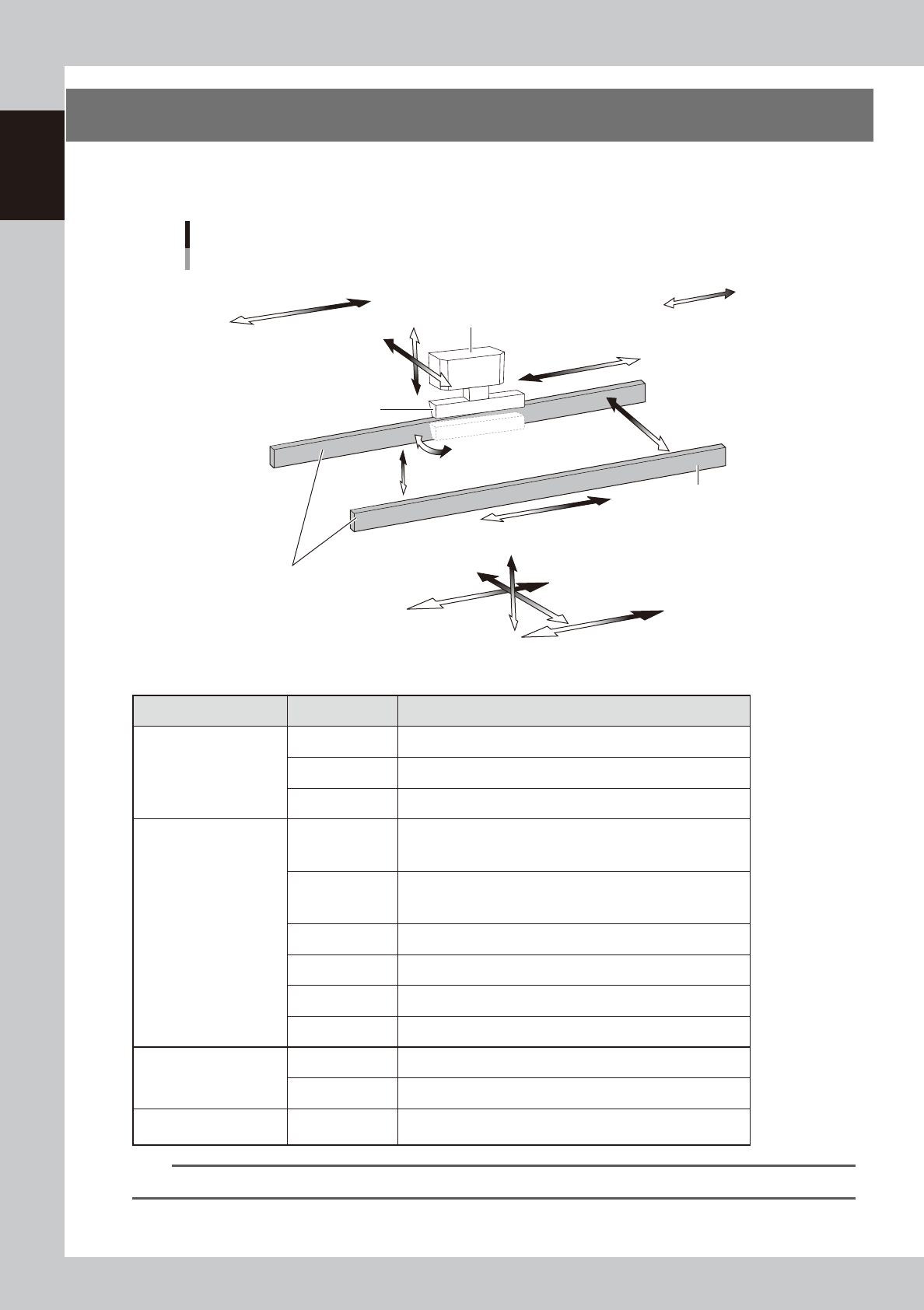
Part names and functions
7. Servo-controlled axes
The mechanical units of this machine move along the following servo-controlled axes. Other mechanical
devices are driven by compressed air.
Servo-controlled axis configuration
Example of right flow
Squeegee head
SY-axis
SZ-axis
CX-axis
Camera unit
Plus direction
Minus direction
Squeegee
Conveyor rail
Board clamp conveyor
(board clamp table)
SR-axis
PU-axis
W-axis
MX-axis
CV-axis
X2-axis
X1-axis
Z-axis
Y-axis
63117-N1-00
n
Axis functions
Unit name Axis Function
Squeegee head
SY Moves the squeegee head parallel to the Y-axis.
SZ Moves the squeegee head vertically.
SR Adjusts the squeegee scraper angle. (3S head only)
Board clamp conveyor
(Board clamp table)
X1
Moves the board clamp table along the X-axis. This X1-axis
synchronizes with the X2-axis to function as R-axis during
operation.
X2
Moves the board clamp table along the X-axis. This X2-axis
synchronizes with the X1-axis to function as R-axis during
operation.
Y Moves the board clamp table along the Y-axis.
Z Moves the board clamp table vertically.
PU Raises and lowers the push-up plate.
MX Moves the mask camera along the X-axis.
Conveyor
W Changes the conveyor width.
CV Convey boards on the conveyor.
Camera unit CX
Moves the board camera and print-inspection camera along the
X-axis.
TIP
You can manually move each unit on the operation screen. See "4.1 "Move Axis" screen" in Chapter 7 for more details.

Chapter 2 Basic operations
This chapter explains how to start up the machine and power off, as well as basic menus displayed on the operation screen.
We recommend you read this chapter while actually operating the machine as instructed.
Contents
1.
Canceling emergency stop/clearing error 2-1
1.1 Canceling emergency stop 2-1
1.2 Clearing an error 2-2
1.3 Typical errors and troubleshooting 2-3
2. Starting and stopping the machine 2-7
2.1 Inspecting before operation 2-8
2.2 Starting the machine 2-9
2.3 Powering off the machine 2-11
3. Operation screen description 2-13
3.1 Basic configuration of operation screen 2-13
3.2 Various buttons and parameter input grids 2-14
2-1
2
Basic operations
1.
Canceling emergency stop/clearing error
The following explains how to cancel emergency stop and clear errors.
1.1 Canceling emergency stop
When the machine is in emergency stop, the red signal lamp on the top of the machine is lit and the red
"EMERGENCY STOP" sign is displayed in the status area of the operation screen. Follow these steps to cancel
emergency stop.
1
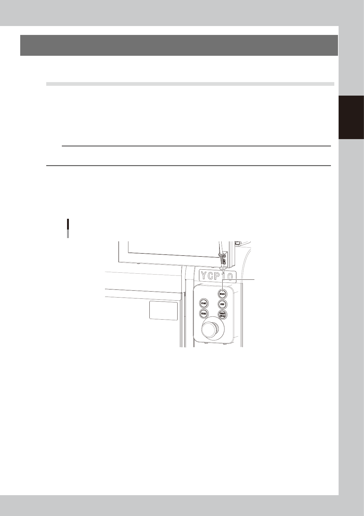
Release the emergency stop button.
When the emergency stop button is pressed (turned on), turn it clockwise to release it. The emergency
stop button is on the operation panel (front upper right).
TIP
When emergency stop was triggered by a safety interlock switch, first eliminate the cause of emergency stop and
then cancel it.
2
Check safety.
Before continuing the procedure, check the surrounding area for safety.
3
Press the [READY] button on the operation panel.
Pressing the [READY] button turns on the servomotors.
[READY] button
[READY] button
63201-N1-00
4
Check the signal light and screen display.
Check that the red signal lamp is off and the emergency stop sign in the upper left (status area) of the
operation screen is now off.